Camera Configuration
How to properly configure the camera in order to get good images.
- Select appropriate lens
- Select Image format
- Select Image size
- Select Frame rate
- Adjust image brightness
- Adjust Focus
- White Balance
- Save settings
Optional:
- Gamma or Contrast stretch
- LUTs
- Sharpening
- Convolution Kernels
- Illumination/Vignetting correction
- Gain map
- Lens distortion correction
- Distortion Map
- Perspective correction
- Distortion Map
- Advanced Color Correction
- Color Correction Matrix
- Synchronization between camera and lights or multiple cameras
Note that the availability of these optional settings is dependant on the used bitstream.
Select appropriate lens
- All qtec camera heads are made with the C-mount type lens mount.
- Check the sensor list in order to
determine the required lens size (based on sensor size)
- fx: 2/3", 1", 1.1"
- Remember to select a lens with the appropriate resolution (pixel size)
- A low resolution lens can result in the blurring of pixels (fx 2Mpx lens on 12MPx sensor)
Selecting focal length
- Desired field of view (FOV) or pixel/mm resolution
- Desired working distance
- Sensor size (image and pixel sizes)
- Image format: Mono vs Bayer (Decimated vs Interpolated)
- Formulas:
focal_length[mm] / sensor_size[mm] = distance_to_object[mm] / field_of_view[mm]sensor_size[mm] = sensor_size[px]*pixel_size[um]*1000resolution[mm/px] = field_of_view[mm] / sensor_size[px]field_of_view[deg] = 2 * atan2(sensor_size[mm]/2, focal_length[mm]) * 180/PI
Select Image format
Different image formats are available depending on the sensor used.
Mono sensors have only grayscale formats, while sensors containing a Bayer filter offer both color and grayscale formats.
The image format is selected through the Pixel Format in v4l2
(VIDIOC_S_FMT) and it is described as a four character (FourCC) code.
--set-fmt-videoinv4l2-ctlPixel Modein the web interface (underCamera Settings)set_format()inqamlib
See Video for Linux API - Image Formats for the lists of possible fourcc codes (divided by RGB, YUV, ...).
For example:
- Color
- Singleplane
V4L2_PIX_FMT_BGR24('BGR3')V4L2_PIX_FMT_RGB24('RGB3')V4L2_PIX_FMT_YUV32('YUV4')V4L2_PIX_FMT_YUYV('YUYV')
- Multiplane
V4L2_PIX_FMT_NV12('NV12')
- Singleplane
- Bayer
V4L2_PIX_FMT_SRGGB8('RGGB')V4L2_PIX_FMT_SGRBG8('GRBG')V4L2_PIX_FMT_SGBRG8('GBRG')V4L2_PIX_FMT_SBGGR8('BA81')
- Greyscale
V4L2_PIX_FMT_GREY('GREY')V4L2_PIX_FMT_Y16('Y16 ')V4L2_PIX_FMT_Y16_BE('Y16 ' | (1 << 31))
The list of available formats for the current sensor can be obtained through
the VIDIOC_ENUM_FMT v4l2 ioctl.
Grayscale formats
Available both in Mono and Bayer sensors.
Grayscale formats are available with either 8 or 16 bit depth. When 16-bit formats are used it is important to chose both the bit mode and the bit order.
- 8-bit
- 16-bit
- Bit mode (10 or 12 bits)
- Bit order (LE or BE)
Bit Mode
Different sensors support different bit modes, but mostly: 8, 10 and 12 bit modes are available.
When retrieving 8-bit images there is no real difference in the image itself regardless of the bit mode used, as the extra bits (least significant) are simply discarded.
However when 16-bit images are used the bit mode selected will have a great impact on the real bit depth available as the retrieved bits are bit shifted upwards in order to create a 16-bit image out of 10 or 12 bits of data. The real bits become the most significant ones and the least significant are padded with zeros.
Note that higher bit modes require higher bandwidth, and therefore have reduced framerate.
The bit mode is selected thought the Bit Mode v4l2 control which is a menu
control containing the available bit modes.
Bit Modein the web interface (underCamera Settings)
Byte order (endianess)
When operating with 16-bit images it is important to define their endianess. Which refers to the order or sequence of bytes.
It can be big-endian (BE) or little-endian (LE). A big-endian system stores the most significant byte of a word at the smallest memory address and the least significant byte at the largest. A little-endian system, in contrast, stores the least-significant byte at the smallest address.
Some file formats require a specific endianess. For example PNM (Portable Any Map) assumes the most significant byte is first (BE). The same is true for PNG, while TIFF's byte order is always from the least significant byte to the most significant byte (LE).
The qt5222 cameras are native little-endian (LE) but can produce 16-bit grayscale images in both big-endian (BE) and little-endian (LE) formats.
The byte order is selected at the same time the format is selected, it is part of
the fourCC code: V4L2_PIX_FMT_Y16 ('Y16 ') vs
V4L2_PIX_FMT_Y16_BE ('Y16 ' | (1 << 31)).
Color Formats
Available only in sensors that have a Bayer filter.
Since a Bayer filter is present it is necessary to demosaic the data in order to extract a color image. Two demosaic methods are currently available: decimation and interpolation.
The demosaic method is selected through the Bayer Interpolator Mode v4l2
menu control (in available bitstreams).
If this control doesn't exist the demosaic method defaults to decimation.
It is also possible to retrieve the RAW Bayer image in order to perform
demosaicing as a post-processing step.
This can be done by selecting a bayer format as the pixel format
(fx 'BA81' which is BGGR).
Bayer filter (en:User:Cburnett, Bayer pattern on sensor, CC BY-SA 3.0)
The native colorspace is RGB but some colorspace conversions are available depending on the bitstream used (RGB, BGR, YUV, HSV, ...).
Bayer Decimation (subsampling)
Comparable to nearest neighbor interpolation.
Reduces the image resolution by half in both directions (1/4 of total pixels) by only using the available data (no interpolation). It takes each color pixel from the bayer array (2x2 group) and makes into a single 3 channel (RGB) pixel. Since there are 2 green pixels available they get averaged together.

Can result in color artifacts (false coloring) along edges.
Color artifacts from decimation
Bayer Interpolation
Bilinear interpolation. Keeps then image resolution by interpolating the values in between the bayer pixels.

Can present color artifacts (false coloring and "zippering") along edges.
 Color artifacts from interpolation
No edge-aware demosaicing methods are currently available on the FPGA.
Colorspaces
Native RGB (from Bayer filter).
Depending on the application it can be advantageous to perform colorspace conversion directly on the FPGA in order to obtain images with a different color format.
The most simple conversion is inverting RGB to BGR (normally used in OpenCV). And it is also possible to add an empty alpha channel.
Other conversions include HSV and different types of YUV (NV12, ...). YUV formats are normally required for video encoding (fx H264).
The colorspace is selected at the same time the format is selected, it is part
of the fourCC code: V4L2_PIX_FMT_BGR24 ('BGR3') vs
V4L2_PIX_FMT_RGB24 ('RGB3') vs V4L2_PIX_FMT_NV12 ('NV12').
Note that most formats are single plane while others can be multiplanar, like NV12.
Select Image size
The image size is part of the image format, and is therefore also set through
the VIDIOC_S_FMT ioctl from v4l2.
The image size influences the maximum possible framerate and bandwidth.
If the image size used is smaller than the sensor size the image area will be
taken from the left-top corner of the sensor by default.
It is possible to control this behavior by changing the desired cropping area,
which is done by specifying the left and top coordinates of the image area,
relative to the sensor.
It is also necessary to specify the width and height of the cropping area,
which in most cases should match the width and height selected in the image
format.
If the sizes don't match the cropping area might be rejected.
The exception to this rule is in cases where line skipping or binning might be
desired (and will have to be properly configured).
The cropping is controlled through the
v4l2 selection interface
(VIDIOC_S_SELECTION).
--set-cropinv4l2-ctlImage Sizetab in the web interface (underCalibrations)set_crop()inqamlib
In most cases a single cropping area is used. But it is also possible to specify multiple areas (up to 8), which might have some constrains. In CMV sensors the left and width of all areas must be the same, only the top and height of each can be individually controlled.
Note that when changing cropping it is necessary to first adjust the image size
in the image format (VIDIOC_S_FMT).
The set_crop() function from qamlib automatically adjusts that in order to
aid the user, the same happens in the Image Size tab of the web interface
(under Calibrations).
Select Frame rate
Limits the maximum exposure time possible.
Controlled through the VIDIOC_S_PARM ioctl from v4l2.
--set-parminv4l2-ctlFrame Ratein the web interface (underCamera Settings)set_framerate()inqamlib
The max framerate available is dependant on image size, pixel format and
bit mode.
It is possible to query the possible frame intervals based on the pixel format
and image size using the VIDIOC_ENUM_FRAMEINTERVALS v4l2 ioctl.
--list-frameintervalsinv4l2-ctl
Adjust Image brightness
Maximize the dynamic range while avoiding overexposure and limiting noise and motion blur.
Adjust aperture
The lens aperture is usually specified as an f-number: the ratio of focal length to effective aperture diameter. A lens typically has a set of marked "f-stops" that the f-number can be set to. A lower f-number denotes a greater aperture opening which allows more light to reach the film or image sensor. The photography term "one f-stop" refers to a factor of √2 (approx. 1.41) change in f-number, which in turn corresponds to a factor of 2 change in light intensity.
- bigger aperture (smaller N-number) allows more light inside the sensor
aperture_area[mm²] = pi * (focal_length[mm] / 2*aperture[N])²aperture[N] = focal_length[mm] / aperture_diameter[mm]
- bigger aperture (smaller N-number) reduces the depth of focus (depth of field).
The size of the aperture also has a big impact of the depth of field because it narrows the part of the lens that is used.

The points in focus (2) project points onto the image plane (5), but points at different distances (1 and 3) project blurred images, or circles of confusion. Decreasing the aperture size (4) reduces the size of the blur circles for points not in the focused plane, so that the blurring is imperceptible, and all points are within the DOF.
Depth of Field
Depth of field changes linearly with F-number and circle of confusion, but changes in proportion to the square of the focal length and the distance to the subject. As a result, photos taken at extremely close range have a proportionally much smaller depth of field.
depth_of_field[mm] = 2 * distance_to_object[mm]² * aperture[N] * circle_of_confusion[mm] / focal_length[mm]²
The circle_of_confusion size can be set to the size of 1 or 2 pixels
(pixel_size[mm]).
Use the biggest aperture (smallest N-number) which gives an acceptable depth of focus.
Example
Considering a distance to object of 1m and using a CMV sensor with pixel size
of 5.5um and an 8mm lens.
DOF = 2 * 1000² * N * (2* 5.5/1000) / 8² = 343.75 * N
Therefore with an aperture of N=1.4 the depth of field is ~480mm. While
with an aperture of N=2.8 (2 f-stops difference) the depth of field is double
(~960mm).
Note however that the depth of field is not evenly distributed. In fact the DOF beyond the subject is always greater than the DOF in front of the subject. For large apertures at typical portrait distances, the ratio is close to 1:1.
Adjust Gain and Exposure
- Start with gain: 1x
- reduces noise
- Select exposure time
- influences motion blur
- Adjust gain up if necessary
- also amplifies noise
Note that the GMAX sensors can present image artifacts and incorrect saturation when low gain settings are used (gain < 2x). Therefore it is recommended to keep the gain above or equal to 2x when using GMAX sensors.
Dynamic range
The image histogram can be used to verify if the exposure setting is optimal in relation to maximizing the dynamic range while avoiding overexposure (which results in clipping).
| Over-exposed image | Under-exposed image |
|---|---|
 |  |
The image to the left is over-exposed: parts of the image are oversaturated, which results in clipping of these values. This can also be see in the histogram, which has a very high peak at the right edge (maximum image intensity). The image to the right is under-exposed: it is too dark. And the histogram also shows that the dynamic range is not used fully, only about half of the intensity values are used.
| Intensity (Grey) histogram | Color (RGB) histogram |
|---|---|
 |  |
While the grey histogram is a good indication of the distribution of intensities through the image, it is not completely accurate if the image is not white balanced. The example above shows how one, by looking only at the grey histogram, might think the image to the left is not over-exposed. However by examining the histogram of the separate colors (right image) it can be seen that the green channel is saturated (while red and blue are not).
 Image with good exposure settings (and dynamic range fully utilized)
Motion Blur
How much an object moves during exposure. Will result in blurring artifacts if the object moves more than half a pixel.
motion_blur[mm] = object_speed[mm/s] * exposure_time[ms] / 1000motion_blur[px] = motion_blur[mm] * resolution[px/mm]
Example
If a production line moves with 0.5m/s and the exposure is set to 1ms the
motion blur will be of 0.5mm.
And if the image resolution is 4px/mm the object will have moved 2px.
So a single pixel object will appear as a 3 pixel blur
(with reduced intensity at each pixel).
In order to avoid motion blur the exposure should be reduced to 250us,
so that there is only 0.5px movement during exposure.
Moreover with a framerate of 20fps the movement between frames will be of
25mm (or 100px assuming 4px/mm resolution).
Adjust Focus
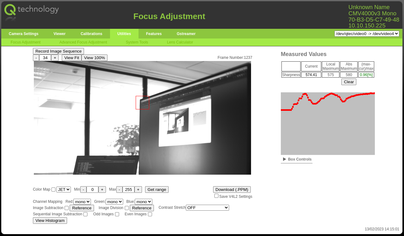
Use the focus helper from the camera web interface under Utilities -> Focus Adjustment (http://<camera_ip>#focus).
It measures the sharpness level inside the marked area (red box) and shows it on a graph on the rigth side. Therefore it is important to move the 'measuring box' to an area which has contrast (edges, text, ...).
Move the focus ring of the lens back and forth and observe the graph. The focus is optimal when the graph reaches its peak.
 Focus Adjustment
Note that the measured values are relative to the scene and dependant on multiple factors (light level, content of the red box, ...) and therefore cannot be compared between different setups. Neither can they be used as an absolute measure of sharpness.
White Balance
Correct the color balance depending on the light source when using a Bayer sensor.
- Requires a Grey calibration card (fx from 'Mennon').
Use the helper from the camera web interface under Calibration -> Color Calibration (http://<camera_ip>#colorCalibration).
Place the grey calibration card under the area marked by the red box (or move
the box to fit) and press 'Auto white Balance'. The web interface will
automatically adjust the Red, Green and Blue gains in order to make the
calibration area contain a color neutral grey color. The color channel with the
highest intensity will be kept at gain 1x and the other two will have their
gains increased.
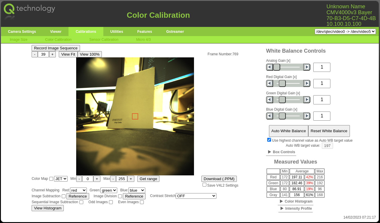
 Before White Balance
It is quite clear that before the white balance the image has a yellow tint. Which is also confirmed by the 'Measured Values' on the table on the bottom right corner. The red and green average intensities inside the calibration box are much higher than the blue (197 and 182 vs 87).
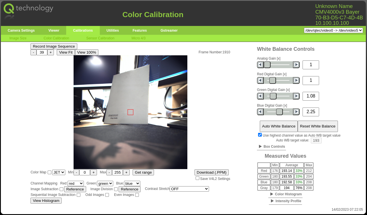
 After White Balance
After the white balance is performed the image has neutral colors. Which is also confirmed by the 'Measured Values' on the table on the bottom right corner. Now all average intensities inside the calibration box are very close to each other (193, 194, 193).
If doing a manual calibration (or color gain adjustment) remember to keep all
color gains above 1x otherwise the colors will be distorted in over exposed
image areas.
Note that this calibration is highly dependant on the light source (color temperature) and therefore must be re-run if the light changes changes.
Save/Load settings
The camera is always reverted to the default driver settings on reboot. Therefore once the camera is properly configured it is important to save the adjusted camera settings (exposure, fps, image size, white balance, etc) in order to be able to restore them after a reboot.
There are currently different possibilities:
Using the Camera Web Interface
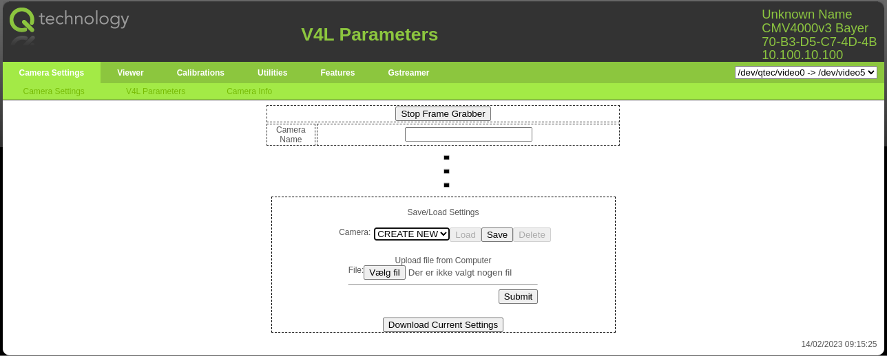
Using the Save/Load interface in the bottom of the camera web interface under
Camera Settings -> V4L Parameters (http://<camera_ip>#v4lParams)
- Produces a XML file which is saved internally on the camera using the
requested file name
- This file can also be downloaded/uploaded from/to the camera
- Restoring the settings is done by manually clicking the
Loadbutton
 Save/Load interface in Camera Web Interface
Using the quark-ctl utility
Using the config option from quark-ctl utility
program.
- Produces a JSON file which is saved internally on the camera on the specified
path (
--fileoption).- If the
--fileoption is not used the default config file will be used
- If the
- Restoring the settings is done by manually running the program with the
loadoption - By default all v4l2 controls and settings (fps, image size/format, ...) are
saved
- But is also possible to specify a sub-set of controls to save/load
quark-ctl config save --file "config.json"
quark-ctl config load --file "config.json"
Init service for default user settings
As mentioned above the camera is always reverted to the default driver settings on reboot. However in some cases it is desired to be able to automatically load user settings on reboot. An 'init service' was created for this purpose.
The service automatically loads the settings present in the default config
file (located under /var/lib/qtec/config.json).
This functionality can be turned on/off by enabling/disabling the service:
systemctl disable quark-config-load
systemctl enable quark-config-load
Using quarklib
If it desired to load specific settings in a qamlib python program it can be done using quarklib.
import quarklib
import qamlib

dev = "/dev/qtec/video0"
config_path = "config.json"

#load settings from config file
quarklib.load(path=config_path, device=dev)

# capture frames
cam = qamlib.Camera(dev)
with cam:
    for i in range(10):
        metadata, frame = cam.get_frame()
        #process frames
        print(metadata)
print("Done")
It is recommended to generate the config file using quark-ctl config save --file 'config.json'.
But it can be generated alternatively by quarklib as well.
import quarklib

#save settings to config file
quarklib.save(path="config.json")
Synchronizing Cameras and/or Lights
Synchronization between multiple cameras and/or lights can be achieved by using the Trigger IN, Flash OUT and Flash OUT #2 camera I/Os as well as selecting an appropriate trigger mode.
The typical use case is to connect the Flash OUT of the master camera to both the Trigger IN of the slaves cameras and to the light system. Then have the master camera use self timed trigger mode and the slaves cameras use either external trigger or external exposure trigger modes. In this way all cameras will capture frames simultaneously and the lights will flash only during frame capture. The master camera will be the one controlling the framerate.
For more complex setups with multiple light sources a trigger sequence can be used.
Refer to Camera/Light Synchronization signals for more details on the I/O signals and to Trigger Modes for more details on the options for trigger modes.
