Hardware Guide
Description of hardware connections on qt5222 camera platform.
Connections
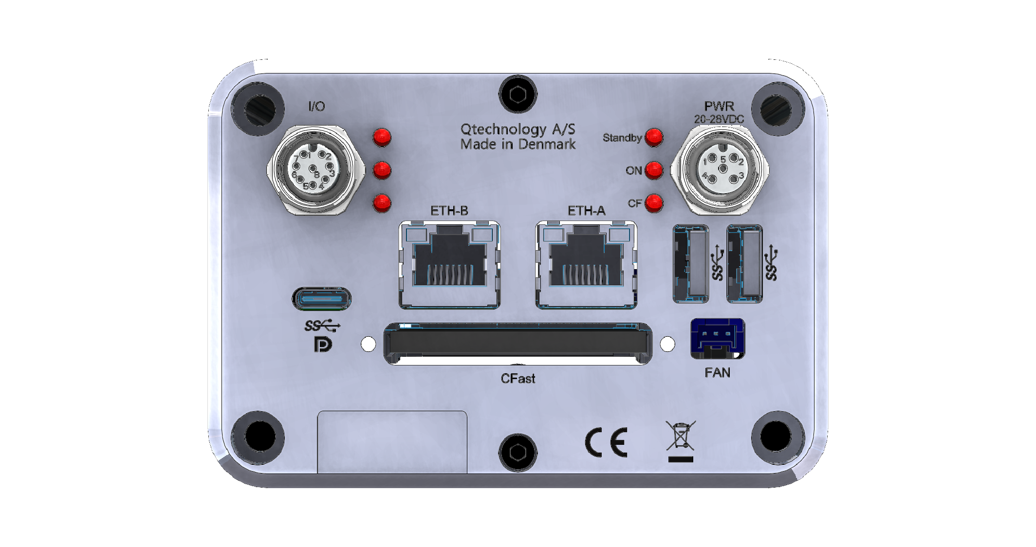
PWR Connector
Used for providing power to the camera.
Optionally used for camera/light synchronization through the Trigger IN and Flash OUT I/Os.
See camera/light synchronization for more details.
| Pin number | Color | Description | Details |
|---|---|---|---|
| 1 | Brown | Power VIN | 24V (min 3A) range: +20V to +28V DC |
| 2 | White | Flash OUT | Push-Pull to 24V, Active LOW (300mA max) |
| 3 | Blue | Ground | None |
| 4 | Black | Trigger IN | Internal Pull-Up to 24V, Active LOW (2.25mA Ilim, Vih=10.5V, Vil=9.2V) |
| 5 | Green+Yellow or Gray | Remote ON/OFF/RESET | None |
- M12 5 pins connector, A-Coded
- PCB connector: Phoenix Contact 1551448
Mating cable from Phoenix Contact:
- SAC-5P-M12MS/1,5-PUR - 1669767
- SAC-5P-M12MS/5,0-PUR - 1669783
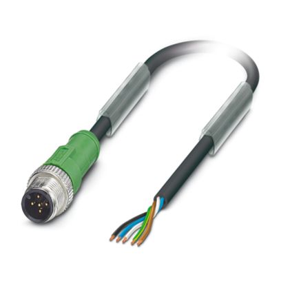
The camera requires a 24V power supply that can handle at least 3A.
I/O Connector
Optionally used for camera/light synchronization through the Trigger IN, Flash OUT and Flash OUT #2 I/Os.
See camera/light synchronization for more details.
| Pin number | Color | Description | Details |
|---|---|---|---|
| 1 | White | Flash OUT | Push-Pull to 24V, Active LOW (300mA max) |
| 2 | Brown | Power VIN I/O | 24V |
| 3 | Green | Trigger IN | Internal Pull-Up to 24V, Active LOW (2.25mA Ilim, Vih=10.5V, Vil=9.2V) |
| 4 | Yellow | RX_IN | Internal Pull-Down, Active High (2.25mA Ilim, Vih=10.5V, Vil=9.2V) |
| 5 | Gray | Remote ON/OFF/RESET | None |
| 6 | Pink | (Not used) | None |
| 7 | Blue | Ground | None |
| 8 | Red | TX_OUT or Flash OUT #2 | Push-Pull to 24V, Active LOW (300mA max) |
- M12 8 pins connector, A-Coded
- PCB connector: Phoenix Contact 1557808
Mating cable from Phoenix Contact:
- SAC-8P-M12MS/ 1,5-PUR - 1522493
- SAC-8P-M12MS/ 5,0-PUR - 1522516
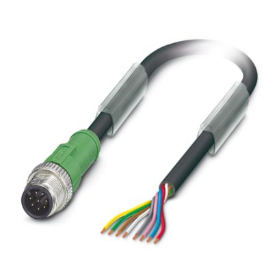
Both PWR and I/O “Power VIN” and “Ground” signals are connected internally on the QT5232 I/O PCB via zero ohm jumpers. We STRONGLY recommend powering the QT5222 from the “PWR” connector.
FAN
The camera also provides a connector that allows powering up a fan for cooling the system.
Refer to the thermal management section for more details on the temperature requirements.
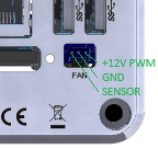
| Pin number | Description |
|---|---|
| 1 | +12V PWM |
| 2 | GND |
| 3 | TACH SENSOR |
- Connector:
- SM03B-PASS-TBT
- Female housing:
- PAP-03V-S
- Female pins:
- SPHD-001T-P0.5
- SPHD-002T-P0.5
The camera kit contains a fan (model nr: 9GA0812P7S001) which has been tested and pre-configured by qtec, but most PC fans should work.
The connector on the camera only has 3 pins while the fan has 4 wires. The PWM wire of the fan is left unused and control of the fan speed is instead achieved by turning it ON/OFF.
Fan BIOS configuration
The control for the fan can be configured through the BIOS.
If fan control is set to auto (the default BIOS option) the fan will be
constantly ON with a fixed speed.
A control table can be used instead in order to achieve a good cooling
performance while minimizing noise.
To enter the BIOS press F2 immediately after the camera has been powered ON.
Navigate to the Fan Table Control tab with the following steps:
AMD CBS → NBIO Common Options → Fan ControlFan Control → <Manual>Fan Table Control → <Manual>
Recommended settings:
| FAN: 9GA08112P7S001 | |
|---|---|
| Low Temperature | 58 |
| Medium Temperature | 62 |
| High Temperature | 65 |
| Critical Temperature | 80 |
| Low PWM | 5 |
| Medium PWM | 8 |
| High PWM | 15 |
| Temperature Hystersis | 10 |
| PWM Frequency | 25kHz |
| Fan Polarity | Positive |
When done configuring the table press F10 to save and exit.
These settings have been determined by testing with the fan included in the camera kit and might need to be adjusted if a different fan is used.
These settings can also be adjusted depending on the operational conditions of the camera, e.g. if more aggressive cooling or a lower noise level is required.
USB-C
The camera provides an USB-C DisplayMode compatible port, that can be used for connecting an external USB-C Monitor. USB-C to DisplayPort or USB-C to HDMI adapters will work as well.
For using DisplayPort Alt-Mode, you need to use a DisplayPort Alt-Mode USB-C cable (there are USB-C cables that can only be used for low USB speed and device charging so make sure you have a video-capable USB-C cable).
It is not possible to hot-plug a monitor to the camera.
The display must be attached to the camera before the camera is booted.
Ethernet ports
The camera has two ethernet 1000Base-T ports (ETH-A and ETH-B).
The default image will have pre-configured a DHCP client for the ETH-A port and a static IP 10.100.10.100 for the ETH-B port.
USB ports
The camera has two USB 3.2 ports which can be used for connecting a keyboard/mouse, USB hub, USB pen-drive for booting/storage, etc.
Default boot order:
- USB
- CFAST
- Netboot
CFast slot
The camera has a CFast slot which can be used for booting the camera or storage.
Default boot order:
- USB
- CFAST
- Netboot
Dual camera setup

The qtec C-series platform offers the possibility of running with a fixed head of your choice ("compact setup"), or with a dual-head cable connector, allowing to connect one or two heads.
Both heads can run independently or can be configured to be synchronized.
The head connected to the PCIe A connector is the master and the one connected to the PCIe B connector is the slave. The Flash OUT pin of the master head is internally connected to the Trigger IN pin of the slave head. All that is necessary in order to synchronize the two heads is to set the slave head to use one of the external trigger modes.
It is also possible to let each head run separately by using the self timed trigger mode for both.
Connecting the heads
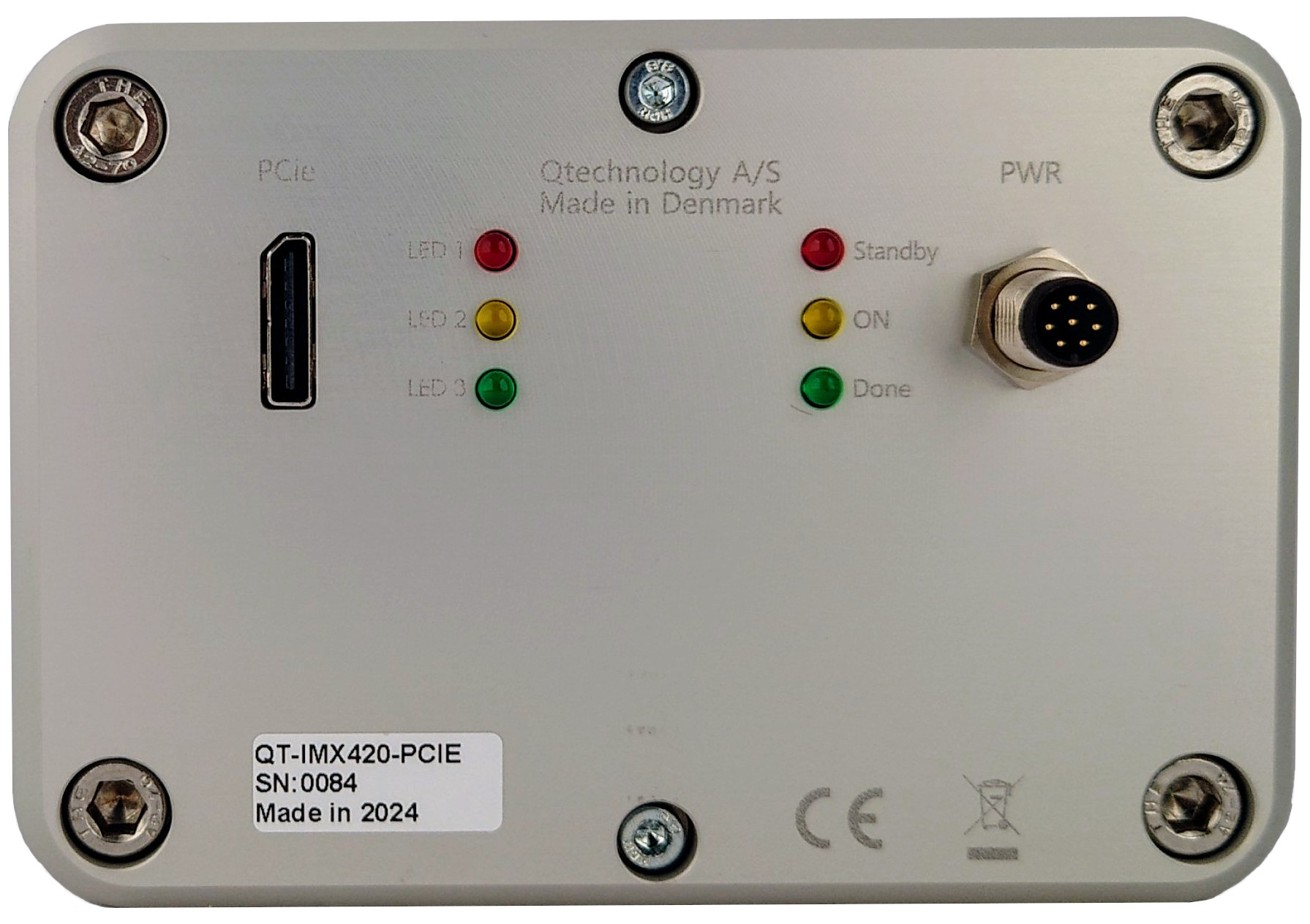
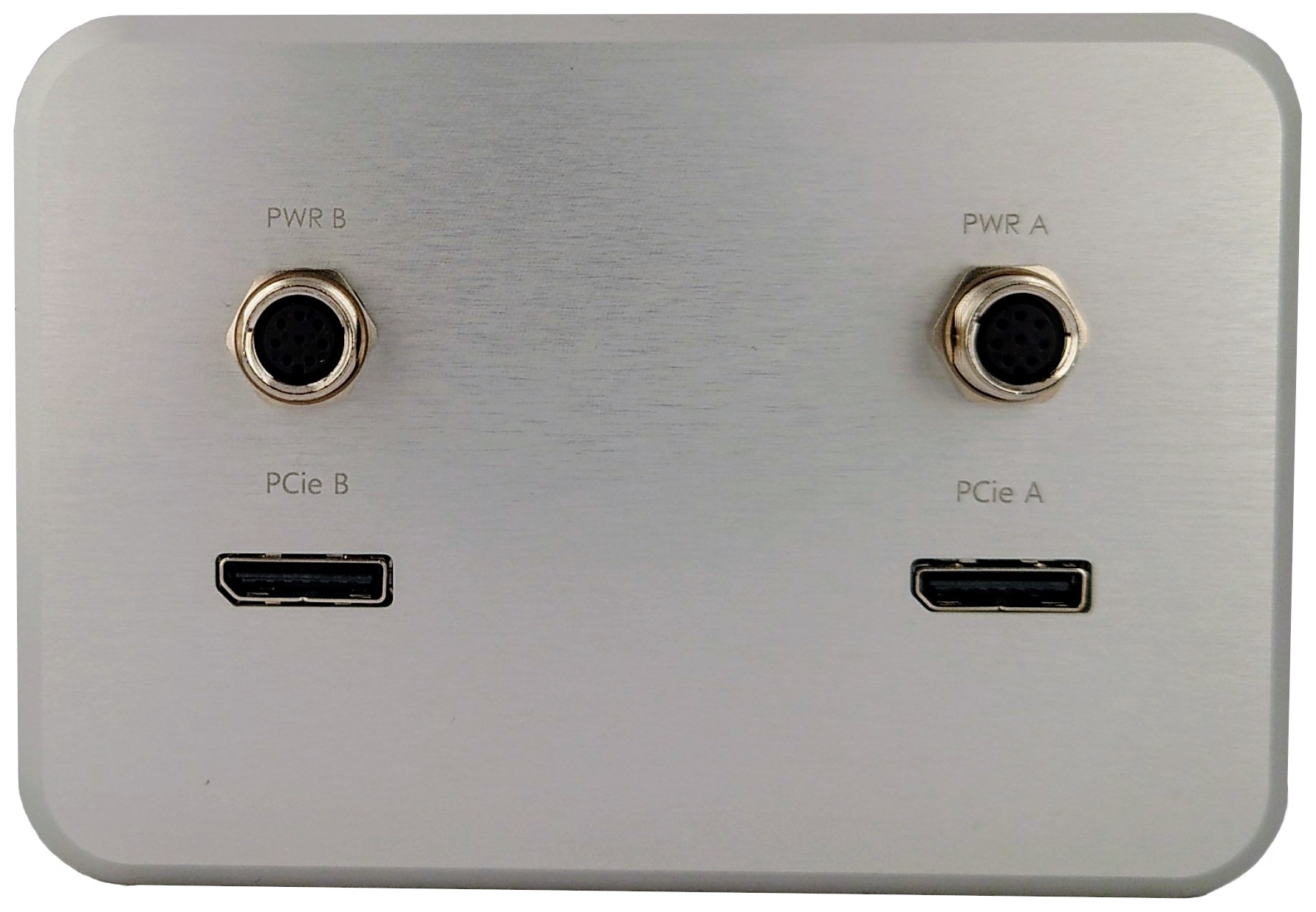
- OCulink cables
- Power cables
- PCIe A -> "master" head
- Flash OUT internally connected to Trigger IN of "slave" head (PCIe B)
- PCIe B -> "slave" head
- Trigger IN internally connected to Flash OUT of "master" head (PCIe A)
Status LEDs
The LEDs on the camera reflect the status of the camera.
They are placed on the back of the camera body for a single-head camera and on the rear of the individual heads for a dual-head setup.
| Color | Left | Right |
|---|---|---|
| Red | Frame dropped | Standby |
| Yellow | Frame captured | ON |
| Green | Heartbeat | CFast(body)/DONE(head) |
Left (I/O side)
| Color | Function | Status | Description |
|---|---|---|---|
| Red | Frame dropped | Blink | Blinks When a frame is dropped by the driver. (frames are dropped if the internal queue gets filled up: not read out fast enough) |
| Yellow | Frame captured | Toggle ON/OFF | Toggles for each captured frame |
| Green | Heartbeat | Blink | Blinks to indicate the camera has finished booting and the FPGA is running properly |
| OFF | The camera has not finished booting or has crashed | ||
| All LEDs | Failure | ON simultaneously | Indicates failure condition |
The streaming related LEDs (red and yellow on left side) only work if the camera is currently streaming.
Streaming does not start automatically when the camera boots. It is for example started when the web interface is accessed and stops automatically when the web interface is no longer in use. It can also be started by running a custom program with an image capture loop.
Right (PWR side)
| Color | Function | Status | Description |
|---|---|---|---|
| Red | Standby | ON | PWR IN is OK, and internal power supply is OK |
| OFF | No PWR IN or failure in internal power supply | ||
| Slow blink | The CPU temperature is too high (the lifetime of the electrical components will be reduced) | ||
| Fast blink | The CPU temperature is dangerously high (the CPU performance is greatly reduced and shutdown is imminent) | ||
| Yellow | ON | ON | Camera is running |
| OFF | Camera is sleeping | ||
| Green | CFast (body) | Blinking | CFast communication (SATA) |
| DONE (head) | ON | FPGA configured and working properly | |
| OFF | FPGA configuration failed (manual reprogramming required) |
Refer to the thermal management section for more details on the temperature thresholds.
Camera/Light Synchronization signals
The Trigger IN, Flash OUT and Flash OUT #2 I/Os from the PWR and/or I/O connectors can be used for synchronization between multiple cameras and/or lights.
Refer to the Synchronizing Cameras and/or Lights section for more details on the general concept.
Trigger IN signal
Camera input signal used for triggering frame capture.
The Trigger IN signal is 24V active low.
By default the camera runs in self-timed trigger mode. It means that the frame capture is governed by the configured framerate, and therefore frames will be automatically captured at a fixed time interval.
If the trigger mode is instead changed to one of the external trigger modes (external trigger, external exposure or external trigger sequence) the camera will capture a new frame whenever it detects a falling edge on the Trigger IN signal. In case the external exposure trigger mode is used the duration of the pulse determines the exposure time.
Refer to the Trigger Mode section for more details on the differences between the trigger modes.
We recommend having a pull-up resistor in the Trigger IN signal in order to avoid false triggers caused by noise.
It is possible to invert the polarity through the Invert Trigger Polarity
V4L2 control.
Remember to also swap the pull-up resistor for a pull-down in this case.
Note that even when operating in one of the external trigger modes the camera cannot capture frames faster than the maximum framerate of the self timed mode (which is limited by the read-out time of the sensor).
Trigger signals received more often than what the camera can handle will be ignored.
Flash OUT signal
Camera output signal used for triggering lights or other cameras.
The Flash OUT signal is 24V active low.
Whenever the camera captures a frame it generates a "negative" pulse on the Flash OUT pin. The pulse has the duration of the exposure time. This signal can be connected to the Trigger IN pin of other cameras in order to synchronize frame capture between the cameras. This signal can also be used to trigger a light system in order to synchronize the light output with frame capture.
We recommend having a pull-up resistor in the Flash OUT signal in order to avoid false triggers caused by noise.
- It is possible to invert the polarity through the Invert Flash Polarity V4L2 control.
- Remember to also swap the pull-up resistor for a pull-down in this case.
- It is possible to disable the output through the Disable Flash V4L2 control.
There is a limit on how many cameras/lights the Flash OUT signal can drive (300mA max).
Secondary Flash OUT signal
Camera secondary output signal used for triggering a secondary light source. Requires the camera to be configured for multiple sequential exposures by setting the trigger mode to trigger sequence.
This can for example be used to take two sequential images with two different light sources (e.g. RGB and NIR) if the 1st light source is connected to the Flash OUT pin and the 2nd light source is connected to the Flash OUT #2 pin.
The Flash OUT #2 signal is 24V active low.
We recommend having a pull-up resistor in the Flash OUT #2 signal in order to avoid false triggers caused by noise.
Thermal management
The CPU of the camera is rated for an absolute maximum of 100°C, however it should be kept at a maximum of 60 to 70°C in order to ensure proper camera performance and prolong the lifetime of the internal components.
The working temperature range for the camera is from 0 to 45°C (ambient temperature). However, the camera CPU can get much hotter than the surrounding air, therefore cooling is generally necessary in order to keep the camera from overheating.
The temperatures of the CPU and GPU can be retrieved by running the following command:
root@qt5222:~# sensors
k10temp-pci-00c3
Adapter: PCI adapter
Tctl:         +42.5 C

amdgpu-pci-0600
Adapter: PCI adapter
vddgfx:           N/A
vddnb:            N/A
edge:         +42.0 C
k10 is the AMD CPU.
The camera provides a built-in connector for powering and controlling a fan for cooling. A default fan is shipped with the camera. Refer to the FAN section for more details.
For optimal cooling the fan should be placed on the "bottom" side of the camera, since this is the area where the CPU internal heatsink is connected to the camera case. Refer to the platform section for an image illustrating the camera architecture and the CPU placement. The fan should also be placed relatively close to the camera in order to be able to force air to flow through the camera profile "cooling fins".
The CPU will automatically throttle down and eventually shutdown (in order to protect the hardware) if certain temperature thresholds are reached. Note that the CPU throttling is very agressive once the temperature reaches 90°C and the camera performance will be greatly limited (making it unsuitable for running applications).
The standby LED state is used to warn the user of the CPU reaching these temperature thresholds.
| Temperature [°C] | CPU [%] | Standby LED |
|---|---|---|
| < 80 | 100 | ON |
| 80 - 89 | 100 | Slow blink |
| 90 - 99 | 80 - 10 | Fast blink |
| >= 100 | Shutdown | ON |
Keep in mind that there are several components inside a camera that produce heat. Apart from the CPU, the GPU and the FPGA can also be a major heat source. No performance degradation is implemented for the GPU and the FPGA.