Quick Start
The Hypervision HSI camera is a push-broom hyperspectral camera based on the qtec C-series platform.
Qtec cameras are full linux computers with image sensors attached, which allows for working either completely outside the camera by streaming the images to a host PC or directly inside the camera doing both the image capture and real-time processing onboard. Both options will be explained in this guide.
Getting Started
What you will need:
- Hypervision camera with appropriate lens
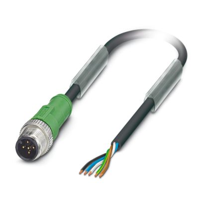
- 24V Power Supply (min 3A) and 5-pole cable
- CFast or USB pen-drive containing qtecOS HSI image
- Ethernet cable (for interfacing with the camera from an external PC)
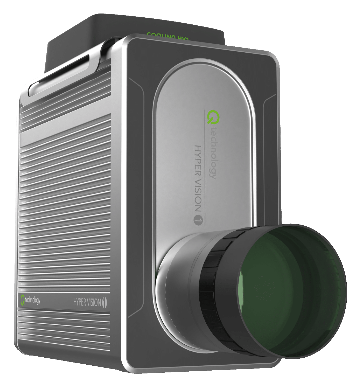
Hypervision camera
There is also the option to work directly on the camera.
The camera provides a USB-C DisplayMode compatible port, so that a monitor can be connected. Furthermore you can connect a USB keyboard / mouse to any of the USB ports or even use a USB hub if you have multiple USB devices.
In order to able to build HSI datacubes:
-
Broadspectrum lighting covering the desired wavelength range (for example halogen)
- Hypervision 1000: 430 - 1000nm
- Hypervision 1700: 430 - 1700nm
-
A transport system for the samples to be scanned (push-broom cameras require the scan object to be translated during scanning)
- for example a conveyor belt or translation stage
- optionally an encoder to measure the belt speed
- for example a conveyor belt or translation stage
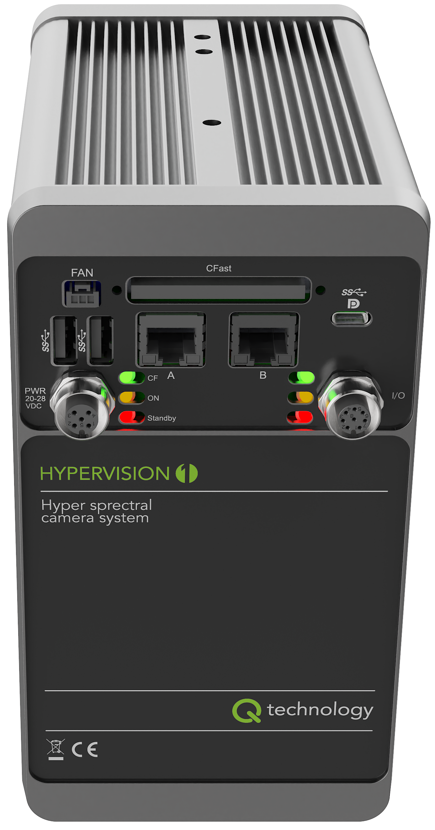
Connections
-
Insert the CFast or USB pen-drive containing the qtecOS image to the proper slot.
-
Connect the ethernet cable to either port A or B depending on the local network topology, see below.
-
Connect a compatible fan to the FAN connector for cooling (highly recommended).
- Optionally connect a screen and a keyboard.
The camera provides an USB-C DisplayMode compatible port, that can be used for connecting an external USB-C Monitor. USB-C to DisplayPort or USB-C to HDMI adapters will work as well.
Note that the camera does not support hot-plugging a screen. It needs to be connected before power is applied.
-
Connect the 24V power supply to the PWR connector using a 5-pole cable (brown: V+, blue: V-).
- The white and black wires are I/Os for light/camera trigger and are not going to be used in this guide. Check the I/O Connector section for more details on the I/O connector (which also has the possibility of connecting an encoder).
Refer to the Hardware Guide for more detailed information on the available hardware interfaces.
Network
The camera has two ethernet ports (ETH-A and ETH-B).
The default image will have pre-configured a DHCP client for the ETH-A port
and a static IP 10.100.10.100 for the ETH-B port.
As a starting point it is easier to just use the ETH-B port (because of its
static IP address) and connect a computer directly to it.
Remember to configure your computer's IP to use the 10.100.10.XXX network as
well.
This can be done in Linux by using the following command as root:
ifconfig <interface name> 10.100.10.200 netmask 255.255.255.0.
Or in Windows: Control Panel -> Network and Internet -> Network Connections,
then select an interface, click Properties.
Set IP address to 10.100.10.200 and Subnet mask to 255.255.255.0.
If it is desired to connect the camera to a local network instead, it should be done using the ETH-A port, and it will get an IP assigned within your organization. Contact your network administrator to find which IP was assigned to the camera or alternatively scan the network for the camera's MAC address.
If DHCP (ETH-A option) is used the IP of the camera can be retrieved with the
ip command, using the monitor and keyboard:
ip a show eth0
Example: 192.168.2.200
Booting
Once power is applied to the camera it will start booting. When the camera has finished booting the green LED on the I/O Connector side will start blinking in a heart-beat fashion. At this point the web interface can be used to see a live preview from the camera, as well as configure camera parameters.
Refer to the Status LEDs section for information on the other status LEDs on the back of the camera.
Camera web UI
The camera web UI is available at the camera IP address.
Assuming a direct connection using ETH-B, the IP is static:
10.100.10.100.
Navigate in your host browser to the url http://10.100.10.100
to access to the Camera interface, which shows a live image stream (MJPEG) and
allows adjusting the different camera controls/parameters like framerate,
exposure time and gain.
Checking the web interface is a good way to ensure that the camera is working properly and that the images look as expected, as well as testing the values of different camera parameters (exposure time, etc).

Camera web UI
Although the web UI also allows for adjusting the image cropping (which can be used to select the available bands) it is not recommended to do this through the web interface as it does not take into account the offset related to the spectral calibration of the camera. It is recommended to use the HV SDK for that instead, as it has direct access to the calibration data.
Refer to the HV SDK camera interface section for more details.
Check the Camera Web UI section for more details on the different functionalities of the web interface.
Acquiring High-Quality Hyperspectral Images
This section provides a step-by-step guide to achieving optimal image quality with the Hypervision cameras.
Follow each subsection in order to ensure your images are sharp, well-exposed, and you have acquired optimal references for future postprocessing (reflectance calibration).
See also the corresponding section of the Buteo user guide.
Adjusting exposure
The first thing that should be done is to adjust the exposure time to a suitable value. The goal is to maximize the intensity without over-exposing any part of the image or any of the wavelengths.
In order to do so an uniform target must be used. The best option is to use a proper white reference board which should optimally cover the whole field of view (FOV) of the HSI camera. RESTAN plates are recommended but other materials, like for example, a white TEFLON plastic plate with a mirror under can also be used. In worst case, a thick stack of A4 printer paper can be used as a rough approximation.
An easy way to check that the image is close to the maximum intensity without over-exposing any wavelength is to use the "Y Intensity profile" tool from the web interface:
- Place the target/reference plate under the camera FOV
- Go to
Calibrations->Color Calibration - Expand the
Intensity Profilesection (bottom right)- choose
y-axisinstead ofx-axis
- choose
- Expand the
Box Controlssection (just above the "Intensity Profile")- adjust the
TopandHeightvalues to cover the whole image height
- adjust the
- Check the graph and adjust the exposure time using a new browser window with
the
Camera settingstab open- increase/decrease the exposure time in order to have the graph as close to the top as possible without having any flat areas on the top (over-exposure).
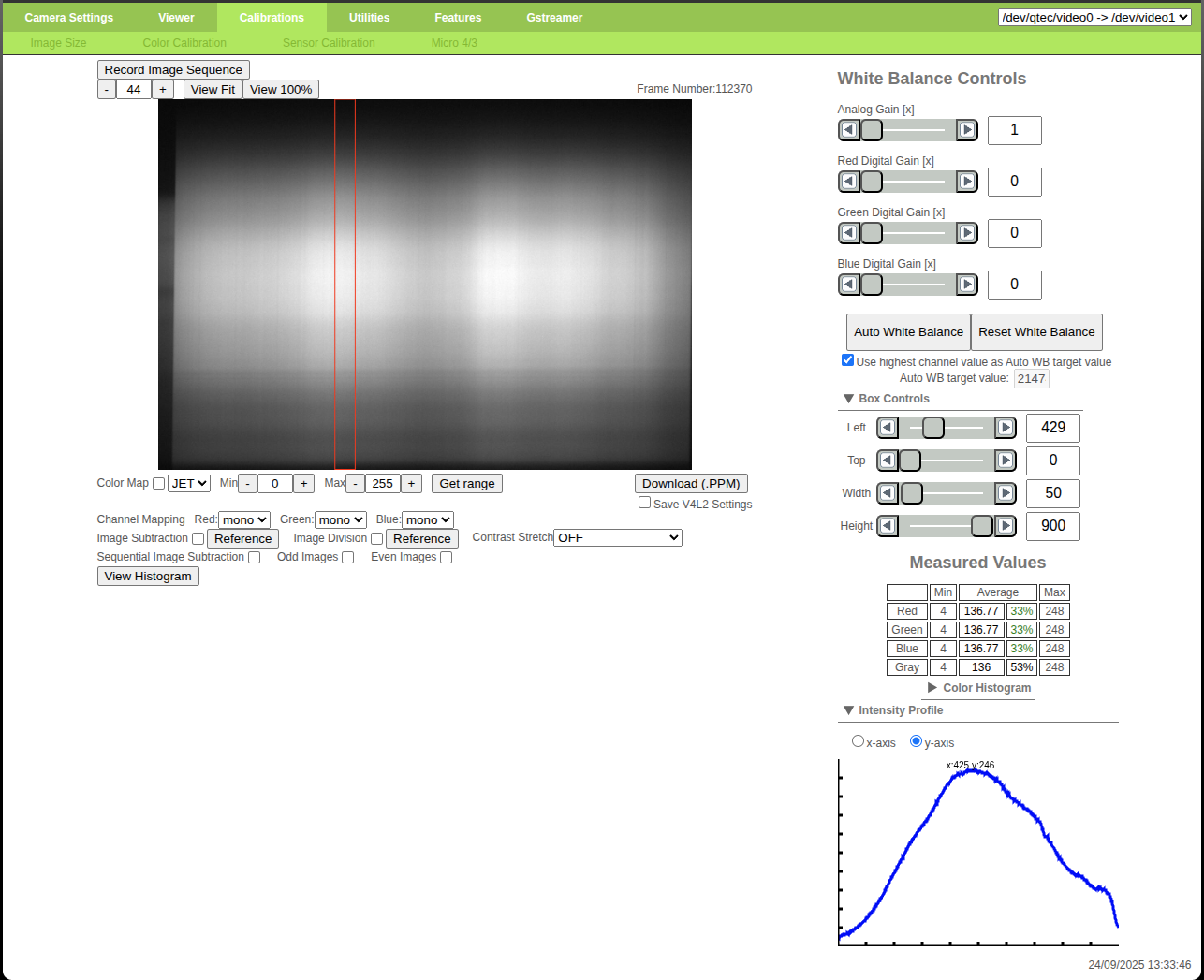
Correct exposure time (max value ~240)
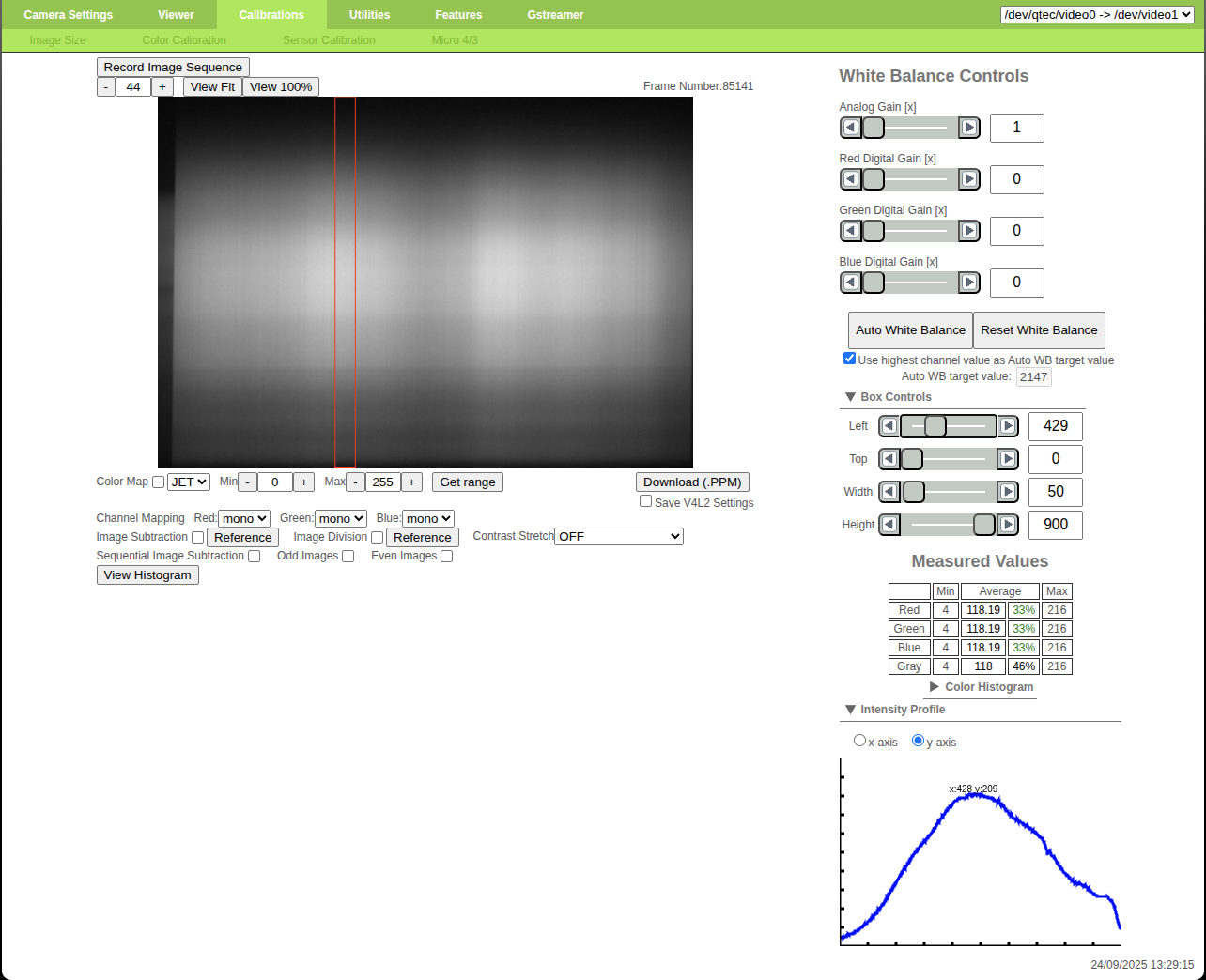
Under-exposed reference (max value ~210)
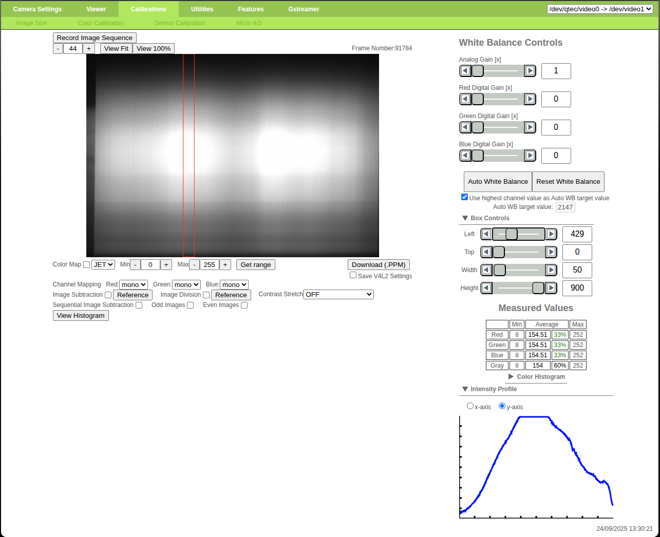
Over-exposed reference (max value >255)
Generally the middle of the image will have the highest intensity and should
therefore be used as the reference area, but depending on the light system used
the light distribution might be different.
In that case the reference area should be adjusted using the Left and Width
controls from the Box Controls section.
After adjusting the exposure time it is recommended to move the measuring area
through all of the image width, using the Left control, in order to make sure
that the sides of the image are not being over-exposed.
Decrease the exposure time if necessary.
Web Interface: adjusting exposure time
It is quite important to maximize the image intensity in order to decrease the effect of noise.
If it is not possible to get the graph to reach high enough values it is necessary to either add more light or to decrease the framerate (in order to increase the maximum exposure time available).
Gain
The Hypervision cameras also have the possibility of adding gain to the images.
However, to minimize noise and maintain a high signal-to-noise ratio, always prioritize increasing exposure before adjusting gain. This is because gain amplifies both the signal and noise, whereas increasing exposure enhances the signal without amplifying noise. For best results, we recommend keeping the gain set to 0 dB (corresponding to no amplification).
Hypervision cameras have their RAW gain values specified in milli dB, therefore the values need to be converted in order to calculate the corresponding amplification.
# converts gain from dB to x
# multiply/divide by 1000 for milli dB
def dB2x(dB):
    return math.pow(10, dB/20.0)

def x2dB(x):
    return 20.0*math.log10(x)
Adjusting focus
Once the exposure time has been adjusted it is necessary to adjust the focus of the lens. An easy way to measure the image sharpness, and therefore its focus, is to use the "Focus Adjustment" tool from the web interface.
- Place a checkerboard target (no specific requirements regarding size) under the camera FOV
- Go to
Utilities->Focus Adjustment - Expand the
Box Controlssection (bottom right)- Adjust
TopandSizein order to cover the whole image height (to measure the focus across all wavelengths)
- Adjust
- Move the lens focus ring while looking at the live graph (which measures the
image sharpness)
- the best focus is when the sharpness is highest
- lock the focus ring in place with its screw
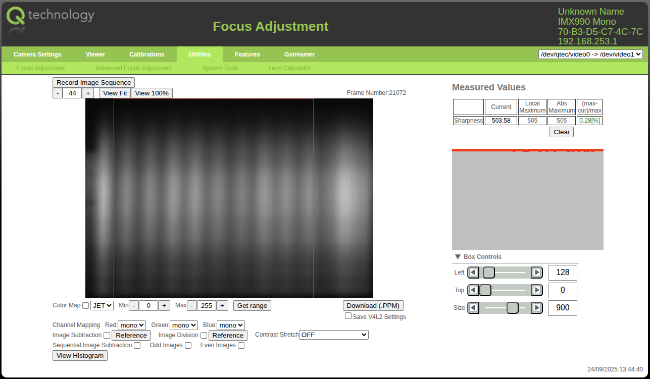
Blurred image
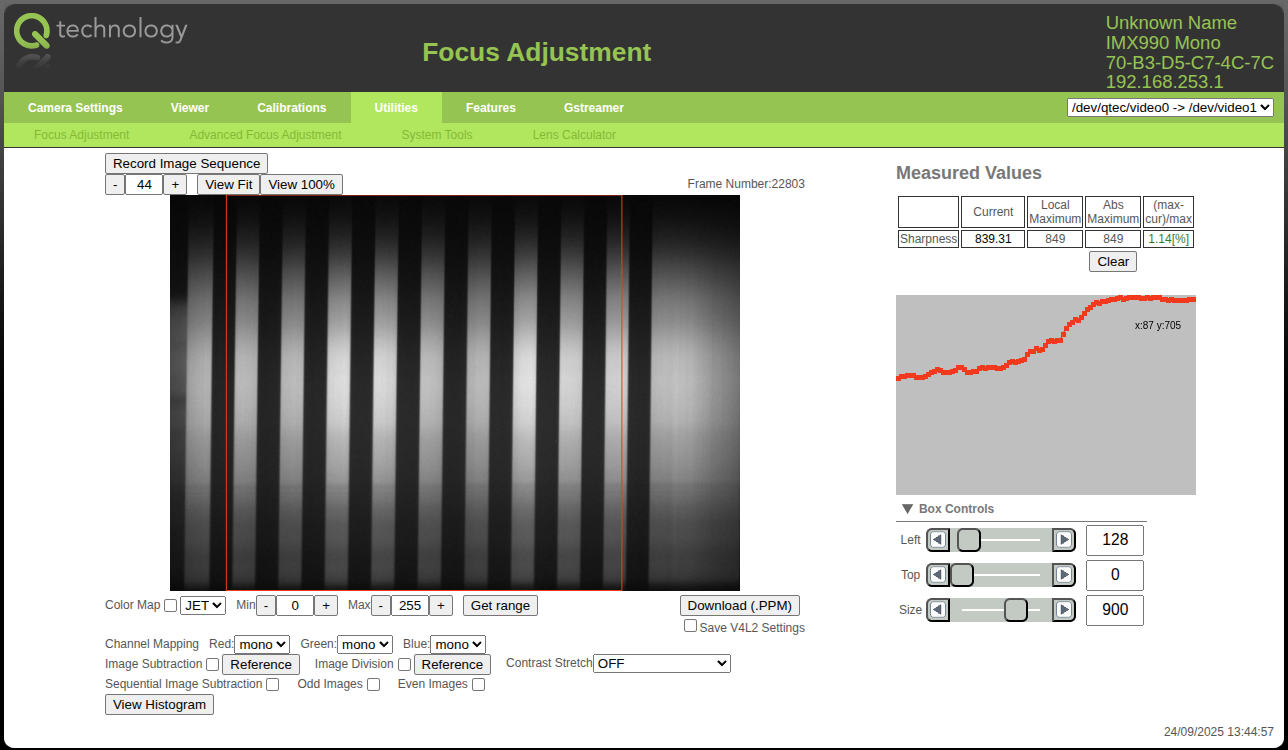
Focused image
Web Interface: adjusting lens focus
After adjusting the focus it might be necessary to tweak the exposure time value.
Re-do the steps from Adjusting exposure and then re-check the focus. Repeat until both stabilize.
F/2.8 is the widest supported aperture for the HV 1700. Do not open the lens wider than F/2.8, because this can introduce optical artefacts and stray light effects in the spectrograph.
If more depth of field is needed, the lens may be closed to a larger F-number. Closing the aperture reduces the light reaching the sensor, so illumination and exposure time may need to be adjusted afterwards.
Reflectance Calibration
Capturing accurate reference images is essential for reliable hyperspectral data processing. Incorrect reference acquisition can result in significant errors during post-processing. Always ensure that reference images are captured using the same bands, gain, and exposure time settings as your sample images.
Acquire both white and dark reference images. Use these files during post-processing to normalize your data and reduce noise. See Reflectance calibration under the HV Explorer section. Or check the same section of the HV SDK guide.
Refer to the Reflectance Model section for more information on the theory behind Reflectance Calibration.
White reference
Like in the exposure time section an uniform reference target must be used.
The best option is to use a proper white reference board which should optimally cover the whole field of view (FOV) of the HSI camera. RESTAN plates are recommended but other materials, like for example, a white TEFLON plastic plate with a mirror under can also be used. In worst case, a thick stack of A4 printer paper can be used as a rough approximation.
Place the target/reference plate under the camera FOV and take a sequence of images (build a datacube), which can later be averaged (during post-processing) in order to reduce the effect of noise. The target doesn't need to move.
Ensure that the reference target is not over-exposed. Refer to Adjusting exposure if necessary.
For maximum accuracy, you can also include the white reference at the edge of your actual sample scans.
In this case choose the "inline" option for the "white reference" in the HV Explorer.
Black reference
Place a lens cap over the camera lens to block all light and take a sequence of images (build a datacube), which can later be averaged (during post-processing) in order to reduce the effect of noise.
Conclusion
Now that the basic image parameters have been adjusted it is possible to start scanning samples and building full datacubes. Remember to note down the exposure time value.
As mentioned in the beginning of the guide, qtec cameras offer the possibility to work both inside or outside the camera hardware itself (do the capture and processing of data on-board or on external HW). The following sections will cover both options.
Working outside the camera
An easy way to start working with the HSI camera is by simply streaming the frames from the camera to an external PC and then doing the processing there.
There are two main software interfaces:
- HV SDK: the recommended interface for camera capture, datacube processing, and Python/C integration. Use this for normal application development. The SDK uses the camera REST API internally.
- REST API: available for custom integrations that need direct access to camera controls, MJPEG preview, or the raw TCP stream, but it is not the recommended path for most users.
The HV Explorer (which is a helper GUI developed by qtec to ease HSI data investigation) is in the process of having an interface to the Hypervision cameras added to it, in order to allow the direct capture of datacubes.
Live data capture support is under active development.
For offline analysis, use HV Explorer to inspect saved datacubes, create ROIs, compare spectra, train supported models, and export annotations or models to the SDK. For scripted or deployed workflows, use the HV SDK.
HV SDK
Camera Interface
The shortest SDK path is to turn the camera into a lazy Image source with
cam.to_hs_image(). After that, camera data can pass through the same SDK
pipeline operations used for file-backed datacubes.
def configure_camera(cam):
    if EXPOSURE_US:
        cam.set_exposure(int(EXPOSURE_US))
    if FRAMERATE:
        cam.set_framerate(float(FRAMERATE))
    if HORIZONTAL_CROP:
        start, end = parse_range(HORIZONTAL_CROP)
        cam.set_horizontal_crop(start, end)
    if BANDS:
        cam.set_bands([parse_range(part) for part in BANDS.split(";")])

# To use a real camera on the default ETH-B address:
# export HSI_EXAMPLE_CAMERA_IP=10.100.10.100
# When this variable is not set, the script uses a simulated camera backed by
# HSI_EXAMPLE_TEST_CUBE. That makes it possible to test the same pipeline
# without camera hardware.
def make_camera():
    if CAMERA_IP:
        cam = hs.control.Camera(CAMERA_IP)
        configure_camera(cam)
        return cam

    test_img = open_test_cube()
    return hs.control.Camera(test_img)


cam = make_camera()

wavelengths = np.array(cam.get_wavelengths())
band_650 = int(np.argmin(np.abs(wavelengths - 650.0)))
print(f"Closest band to 650 nm: {band_650}, wavelength={wavelengths[band_650]:.1f} nm")

# For real cameras, configure exposure, framerate, crop, and bands before
# creating the Image pipeline or starting a direct stream.
img = cam.to_hs_image()
processed = img.ensure_dtype(hs.float32) / 255.0

# The camera pipeline is executed when data is consumed.
# Slice the line dimension first; a live camera stream is otherwise open-ended.
first_lines = processed[:N_LINES, :, :].resolve()
first_band = first_lines[:, :, band_650]

print(f"{first_lines.shape=}")
print(f"{first_band.shape=}")
To run it against a camera on the default ETH-B address:
export HSI_EXAMPLE_CAMERA_IP=10.100.10.100
python 01_camera_pipelines.py
Set camera parameters before capture starts. The same script accepts optional environment variables such as:
export HSI_EXAMPLE_EXPOSURE_US=1000
export HSI_EXAMPLE_FRAMERATE=100
export HSI_EXAMPLE_HORIZONTAL_CROP=200,1200
export HSI_EXAMPLE_BANDS=0,920
If HSI_EXAMPLE_CAMERA_IP is not set, the script uses a simulated camera backed
by an example datacube. See the
Camera Pipelines and
Streaming examples for fuller capture,
calibration, model, and line-by-line streaming workflows.
See also the API docs page on Operations for information on the delayed operations approach that the HV SDK uses for memory efficiency.
When interfacing with the camera from a host PC the data throughput is highly dependent on the speed of the used ethernet interfaces.
It is highly recommended to use a dedicated ethernet connection for the data transfer (for example ETH_B, with a fixed IP), as other existing traffic in the network can greatly decrease the available bandwidth.
The camera has 2x built-in 1Gb/s ethernet ports which gives a theoretical limit of ~120MiB/s, but internal tests showed a more realistic throughput of around ~112MiB/s.
The maximum sensor output of the Hypervision 1700 (153fps with 920 bands) is ~1.3Gb/s which is more than the built-in 1Gb/s ethernet can handle. Therefore operating at full speed will result in frame drops.
To avoid frame drops it is necessary to limit the framerate to a lower suitable value or to use an external interface. It is possible to connect a 2.5Gb/s or a 5Gb/s ethernet adapter to the USB ports on the camera. Our tests have shown that a 5Gb/s adapter can reach speeds of approximately 3Gb/s.
Alternatively it is possible to keep the data capture and processing on-board
by running the HV SDK from inside the camera itself and
connecting to the camera service through localhost / 127.0.0.1.
The same SDK code can therefore run outside the camera with the camera IP, or
inside the camera with localhost. Today this still streams through the camera
service over the REST/TCP interface rather than reading directly from V4L2. For
direct local V4L2 access, use qamlib
and combine it with SDK processing where needed. Direct V4L2 access from the SDK
itself is planned for a future release.
Maximum fps for a 1Gb/s connection:
For the IMX990 (in 8-bit mode) with 920 bands and full width (1296px):
Next Steps
After the first camera connection works, continue with the dedicated tutorials:
- HV SDK Tutorials and Examples for calibration, PCA, classification, regression, annotations, and streaming workflows.
- HV SDK Usage Guide for core API concepts such as lazy operations, interleave, camera pipelines, and custom operations.
- HV Explorer Tutorial for GUI-based datacube inspection, ROI annotation, spectra export, and model training.
HV Explorer
Use HV Explorer for interactive exploration of captured datacubes. Use the SDK when the same workflow should be automated, tested, or deployed.
REST API
REST API running on the camera which provides endpoints for both streaming (MJPEG preview and RAW TCP stream) and camera control (adjusting of settings like framerate, exposure time, band selection, etc). Can be used for building external applications which interact with the camera.
Accessible via camera_ip on port 5000.
Though it is possible to control the camera and acquire frames using the REST API the recommended method of interacting with the HSI cameras is via the HV SDK, which is a library developed by qtec for interacting with the Hypervision cameras and HSI data. Note that the HV SDK uses the REST API internally as means of interacting with the camera.
Interactive docs
Accessible at <camera_ip>:5000/docs
- Assuming ETH_B: http://10.100.10.100:5000/docs
Info on RAW streaming
The API provides RAW streaming through a TCP socket on port 12345. When a new client connects, the server sends a header describing the image format, followed by a stream of frames.
The stream header is a binary header in big-endian format, comprised of the following elements (in order):
- Header marker 'STREAM' literal (6 bytes)
- Frame height (2 bytes, uint16)
- Frame width (2 bytes, uint16)
- Frame depth (2 bytes, uint16) (1 if grayscale, 3 if RGB)
- Bytes per element (1 byte, uint8) (1 if 8-bit, 2 if 16-bit)
- End marker 'END' (3 bytes)
Each frame is represented as a byte array in row-major order.
Frame message
Each frame starts with a header marker:
- Marker 'F' (1 byte)
- Total header length (2 bytes, uint16)
- Sequence number (4 bytes, uint16)
- End marker 'E' (1 bytes)
Followed by the raw frame data
HSI frame info
HSI frames are output in BIL interleave type, i.e., each frame is a N_WIDTH x N_BANDS sized byte array in row-major order.
Receiving the TCP stream
"""TCP-based streaming client template for raw camera frames."""
import argparse
import logging
import socket
import time
import numpy as np

BUFFER_SIZE = 2**16

def process(frame: np.ndarray):
    """Custom post processing

    :param frame: Camera frame
    :type frame: np.ndarray

    """
    #cv2.imshow("img", frame)
    #cv2.waitKey(100)
    ...

def client(ip: str, port=12345):
    """Start client streaming from ip:port.

    :param ip: Camera IP
    :type ip: int
    :param port: Camera Port. Defaults to 4400.
    :type port: int

    """
    try:
        with socket.socket(socket.AF_INET, socket.SOCK_STREAM) as s:
            # Connect to the server
            s.settimeout(10.0)
            s.connect((ip, port))

            # Receive the information header
            info = s.recv(16)
            marker = info[:6]
            height = int.from_bytes(info[6:8], byteorder="big")
            width = int.from_bytes(info[8:10], byteorder="big")
            depth = int.from_bytes(info[10:12], byteorder="big")

            n_bytes = int(info[12])
            marker_end = info[13:]

            # Ensure the header markers are correct
            assert marker == b"STREAM"
            assert marker_end == b"END"

            # Determine frame size in bytes and frame dtype
            frame_len = height * width * depth * n_bytes
            dtype = np.uint16 if n_bytes == 2 else np.uint8

            # Measure transfer speed
            n_frames = 0
            alpha = 0.05
            fps = 0
            transfer_speed = 0
            previous = time.time()

            # Receive frames
            while True:
                # Receive the 8-byte frame header first
                header_data = b""
                while len(header_data) < 8:
                    msg = s.recv(8 - len(header_data))
                    if not msg:
                        # Server disconnected
                        return
                    header_data += msg

                # Unpack the header markers and sequence number for verification
                frame_marker_start = header_data[0:1]
                header_length = int.from_bytes(header_data[1:3], byteorder="big")
                sequence_number = int.from_bytes(header_data[3:7], byteorder="big")
                frame_marker_end = header_data[7:8]

                # Assert header markers and length are correct
                assert frame_marker_start == b"F"
                assert header_length == 8 # Expected header length
                assert frame_marker_end == b"E"

                print(f"{sequence_number=}")

                # Receive the full frame data (frame_len bytes)
                data = b""
                while len(data) < frame_len:
                    msg = s.recv(frame_len - len(data))
                    if not msg:
                        # Server disconnected
                        return
                    data += msg

                # Reconstruct the numpy frame array
                frame = np.frombuffer(data, dtype=dtype)
                frame = np.reshape(frame, (height, width, depth))

                process(frame)

                # Update the transfer speed estimate
                total_transfer = frame_len / 2**20
                n_frames += 1
                new = time.time()
                elapsed = new - previous
                previous = new
                transfer_speed = (
                    transfer_speed * (1 - alpha) + total_transfer / elapsed * alpha
                )
                fps = fps * (1 - alpha) + 1 / elapsed * alpha
                print(f"fps: {fps} transferring at: {transfer_speed} MiB/s")

    except ConnectionRefusedError:
        logging.error(
            "Could not connect to server. Are you sure the server is running and is at"
            " the specified address?"
        )
    except (ConnectionAbortedError, ConnectionResetError):
        logging.error("Connection terminated by the server.")
    except TimeoutError:
        logging.error("Connection timed out.")


if __name__ == "__main__":
    logging.basicConfig(level=logging.DEBUG)
    # Create a simple CLI for specifying the camera's address
    parser = argparse.ArgumentParser(prog="TCP Client")
    parser.add_argument("ip", help="The camera's IP address")
    args = parser.parse_args()

    # Start the client
    client(args.ip)
Be aware of data throughput limitations.
MJPEG endpoint
Accessible at <camera_ip>:5000/mjpeg
- Assuming ETH_B: http://10.100.10.100:5000/mjpeg
Control endpoints
Accessible at <camera_ip>:5000/api:
/api/get_frame/{encoding}: get a single frame (RAW, JPEG, PNM, PAM)/api/stop: stop stream/api/v4l2/control/<control_name>: get/set control value/api/v4l2/framerate: get/set framerate
Hypervision specific:
/api/oculus/config: get/set config (spectral calibration)/api/oculus/settings: get/set settings (bands, horizontal cropping, binning and exposure time)/api/oculus/bands: get/set selected bands/api/oculus/crop_dimensions: get crop dimensions (current and max)/api/oculus/wavelengths: get wavelengths/api/oculus/horizontal_crop: set horizontal crop/api/oculus/binning: set horizontal and vertical binning/api/oculus/exposure: set exposure time/api/oculus/default_settings: restore default HSI settings
"""Client to test REST API"""
from requests import get
from requests import post


CAMERA_IP = "10.100.10.100"
PORT = 5000
BASE_URL = f"http://{CAMERA_IP}:{PORT}"
VIDEO_DEVICE = "/dev/qtec/video0"
TIMEOUT = 5

res = get(BASE_URL + "/api/list_devices", timeout=TIMEOUT)
print(res.status_code)
print(res.text)

res = get(BASE_URL + "/api/v4l2/controls?dev=" + VIDEO_DEVICE, timeout=TIMEOUT).json()
if res.status_code == 200:
    print(res.json())

# 'Exposure Time, Absolute'
exposure = dict()
exposure["id"] = 10094850
exposure["name"] = "Exposure Time, Absolute"
res = get(
    BASE_URL + "/api/v4l2/controls" + exposure["id"] + "?dev=" + VIDEO_DEVICE,
    timeout=TIMEOUT,
).json()[0]
res = post(
    BASE_URL + "/api/v4l2/controls" + exposure["id"] + "?dev=" + VIDEO_DEVICE,
    json={"value": 3000},
    timeout=TIMEOUT,
)
res = get(
    BASE_URL + "/api/v4l2/controls" + exposure["name"] + "?dev=" + VIDEO_DEVICE,
    timeout=TIMEOUT,
)
res = post(
    BASE_URL + "/api/v4l2/controls" + exposure["name"] + "?dev=" + VIDEO_DEVICE,
    json={"value": 5000},
    timeout=TIMEOUT,
)
print(res.status_code)
print(res.text)

res = get(BASE_URL + "/api/v4l2/resolution?dev=" + VIDEO_DEVICE, timeout=TIMEOUT)
res = post(
    BASE_URL + "/api/v4l2/resolution?dev=" + VIDEO_DEVICE,
    json={"width": 1024, "height": 1024},
    timeout=TIMEOUT,
)
print(res.status_code)
print(res.text)
On-board processing
Python programming
There are two Python options for running code inside the camera:
- Use the HV SDK with
localhost/127.0.0.1as the camera address. This is the recommended high-level path and uses the same SDK camera, calibration, and processing APIs as code running on an external PC. - Use qtec's V4L2 Python bindings, qamlib, when you need direct local access to the video device and sensor controls.
At the moment, the SDK-on-camera path still streams through the local camera
service over the REST/TCP interface. Use qamlib for direct V4L2 capture, then
hand frames or saved datacubes to the SDK for HSI processing if your workflow
needs that lower-level access. Direct V4L2 access from the SDK itself is planned
for a future release.
You can run programs directly on the camera by connecting a screen and keyboard
or with a ssh connection: ssh root@<CAM_IP>.
The snippet bellow illustrates how to:
- initialize a camera object (by opening the respective video device).
- set and read back a single control: exposure time.
- start an image capture loop
Simple example
import qamlib

# Opens the default video device: /dev/qtec/video0
# if a different video device is desired add it as the argument
cam = qamlib.Camera()

# Try to set exposure time (us)
cam.set_control("Exposure Time, Absolute", 1000)

# read the actual exposure time back from the device
# as the exact requested value might not have been possible
# which causes the value to be adjusted to the nearest possible
exp = cam.get_control("Exposure Time, Absolute")

# Print the exposure time that we ended up with
print(f"Got exposure time {exp}us")

# Start and stop streaming with context manager
with cam:
    meta, frame = cam.get_frame()

    # Frame number since start of streaming
    print(meta.sequence)

    # TODO: process the frame as desired here
For more details refer to the qamlib
section.
Capture datacubes
Refer to the HSI Python Examples
section for a complete example of a datacube capture in python using the
PAM format and qamlib.
You can also install the HV SDK in the camera and access the
camera service using localhost instead of the camera IP. Refer to the
Camera Interface section above for more details.
For workflows that need direct V4L2 capture and SDK processing in the same
script, see the
qamlib capture with SDK processing example.
For most users, start with the SDK camera interface first; use qamlib only
when direct local V4L2 access is required.
Processing data
Refer to the HV SDK Examples section for examples of doing HSI data processing using the SDK (which can run both inside or outside the camera): PCA, classification, regression, etc.
C programming
When developing in C it is necessary to either
cross-compile using the Yocto SDK
or to build directly on the camera
with gcc.
Both qamlib and HV SDK have C/C++ interfaces, so the python examples above should be easy to convert into C/C++.
Hailo Edge AI
Some models of qtec cameras have a Hailo-8 Edge AI chip, which enables AI models to be run efficiently on the camera.
It is possible to check if the camera has a Hailo module installed by running the
following command on the camera: lspci | grep Hailo.
If the hailo module is present the output will be something like:
02:00.0 Co-processor: Hailo Technologies Ltd. Hailo-8 AI Processor (rev 01)
Refer to the AI camera section for more information.
Flashing a qtecOS Image
The camera development kit includes a pre-flashed CFast or USB pen-drive with the qtecOS HSI image.
Refer to the qtecOS Image section if you don't have such a disk or if you wish to flash a new one yourself.
The CFast card delivered with the development kit contains all the camera factory calibration files. If a new disk is created the calibrations files will need to be copied over as well. Contact qtec for assistance with restoring the factory calibration.
Installing new packages
Qtec cameras have their own package repository.
New packages can be installed or existing ones updated using apt.
Refer to the qtecOS Update section for more details.