Buteo Hyperspectral Equipment
This guide provides step-by-step operational instructions for capturing high quality images using the Buteo Hyperspectral Imaging System. It focuses on how to properly place objects for imaging, aquire proper calibration references, adjust exposure and gain, set conveyor belt speed, and focus the lens.
Calibration procedures and post-processing are not covered here; for those topics, see HSI data processing and HV Explorer.
Software Interface Overview
The Buteo Hyperspectral Imaging System is operated through a dedicated software interface. This section provides annotated screenshots of the primary interface features, along with explanations of each function. Key operational features are described in detail in the subsequent sections.
Please note that the software is regularly updated, so the interface visuals and features may vary slightly depending on your Buteo system version.
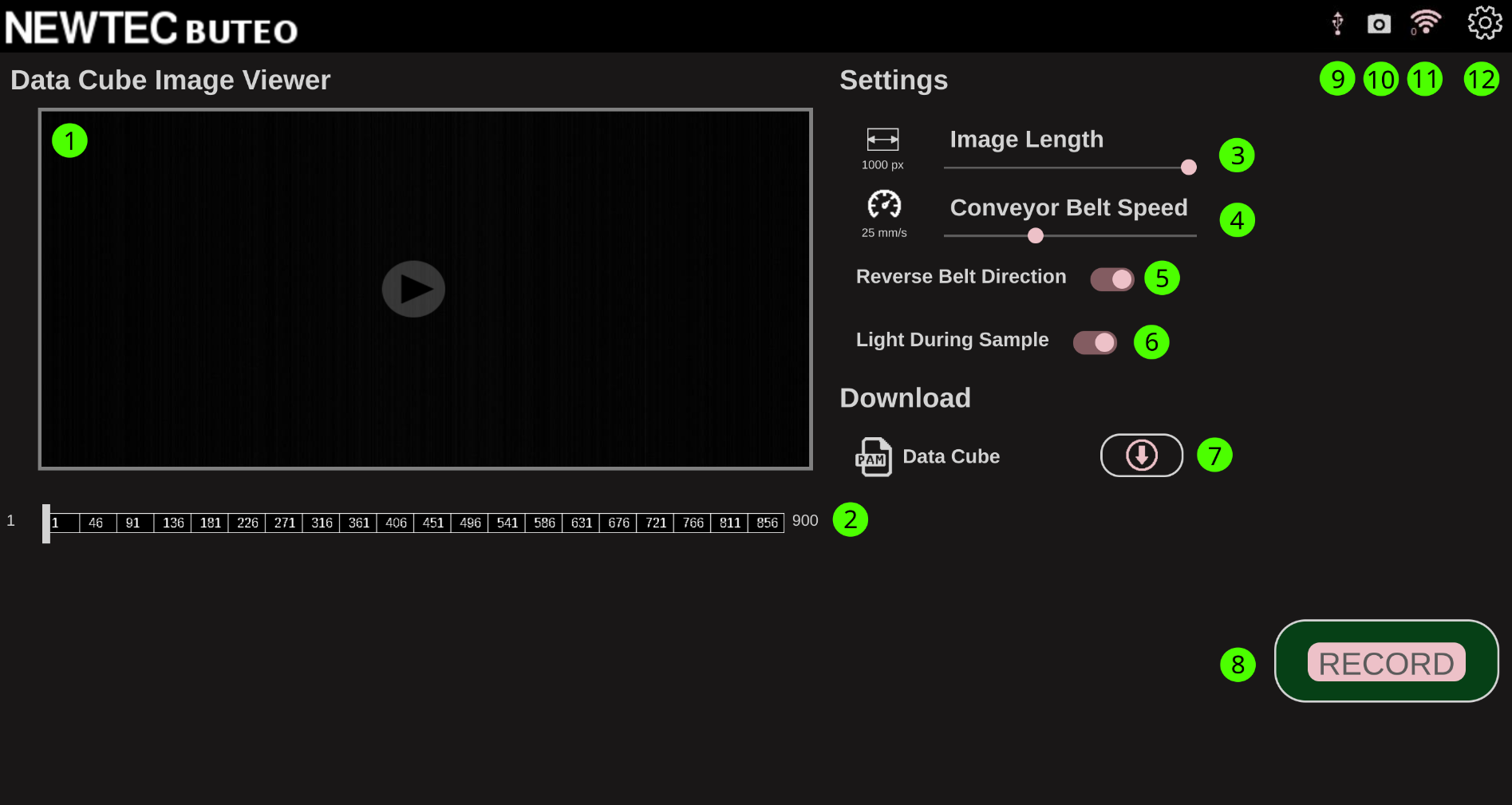
1. Main Capture Screen
| Number | Name | Description |
|---|---|---|
| 1 | Viewing Panel | Displays the most recently captured hyperspectral image |
| 2 | Channel Slider | Adjusts the spectral channel displayed in the viewing panel |
| 3 | Image Size | Sets the number of lines captured during scanning |
| 4 | Conveyor Belt Speed | Controls the conveyor belt speed during image acquisition |
| 5 | Scan Direction | Allows selection of the scanning direction |
| 6 | Light During Sample | Toggles illumination during scanning |
| 7 | Download | Enables downloading of the latest captured image to USB or local storage via Ethernet |
| 8 | Record | Initiates hyperspectral scanning with the current settings |
| 9 | USB Attached | Indicates when a valid USB device is connected |
| 10 | Camera State | Displays camera readiness; grey indicates the camera is not ready |
| 11 | Wi-Fi Connection | Shows the status of the wireless network connection |
| 12 | Settings Menu | Opens the settings menu |
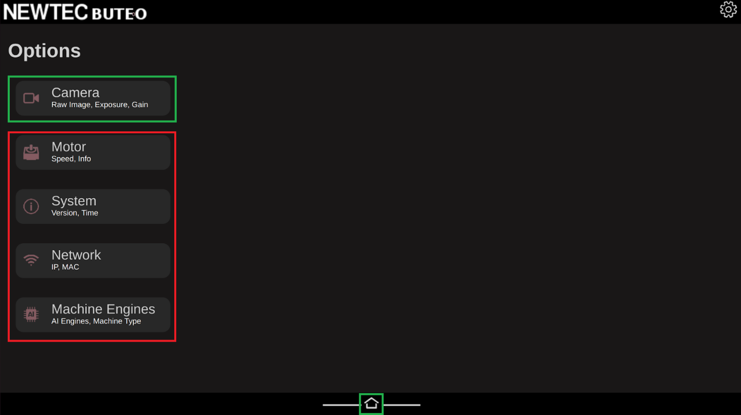
2. System Settings Screen
Selecting the gear icon (item 12 above) opens the settings menu shown below.
Options highlighted with a red rectangle are of little interest to the standard user and should in most cases be left alone. The green rectangle at the bottom returns you to the main screen, while the camera icon at the top left navigates to the camera’s live view screen, described in the next section.
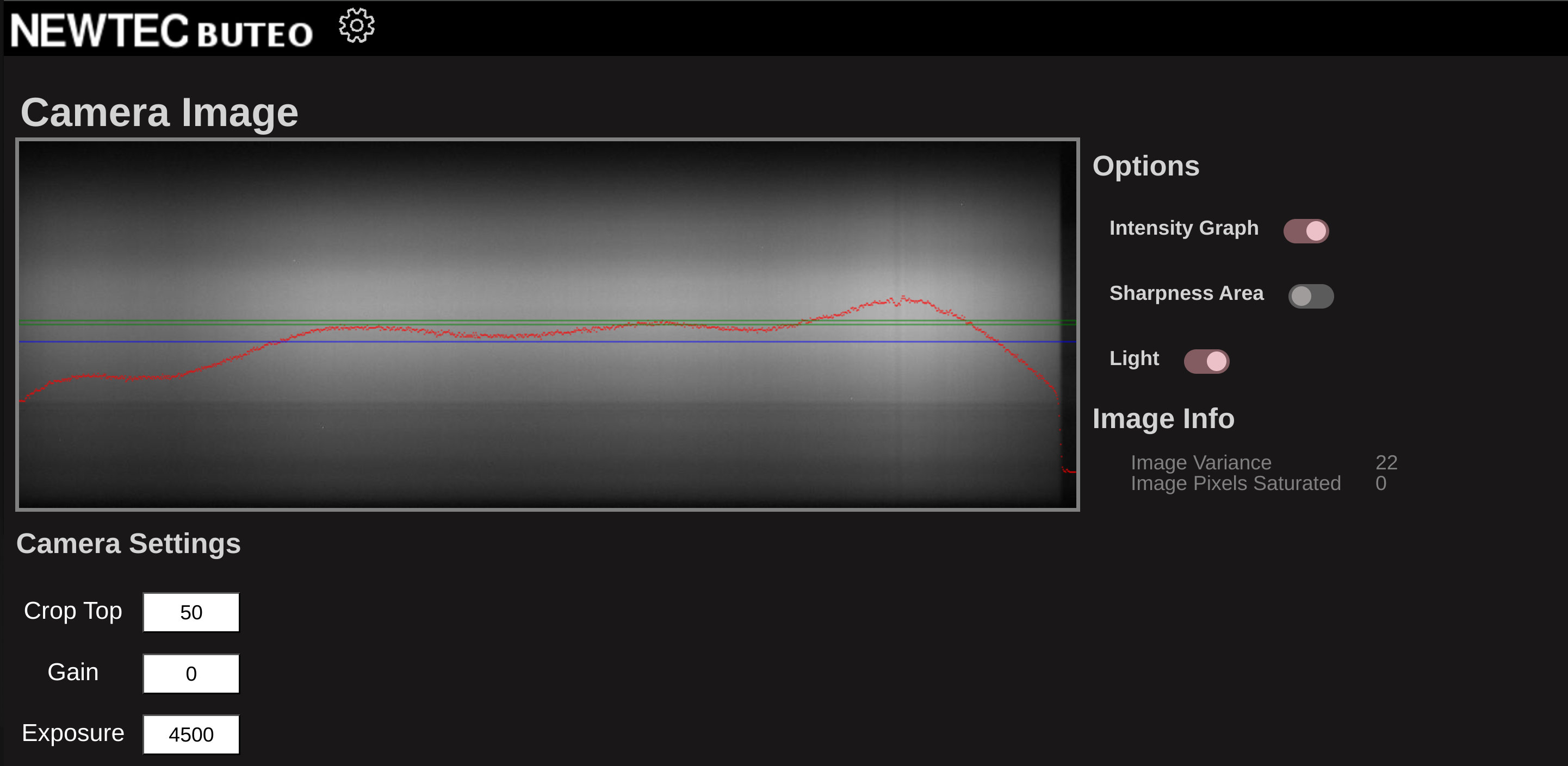
3. Camera Live View Screen
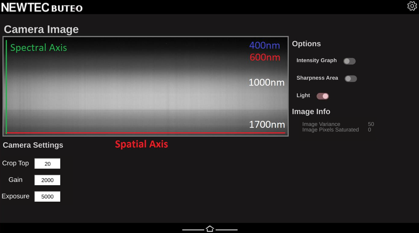
This is the camera's live view screen, where key camera settings are adjusted before scanning. Three main parameters can be set here:
- Crop-Top: Defines the starting coordinate on the camera sensor for pixel readout. Incorrect adjustment may exclude parts of the spectral range (430–1700 nm).
- Gain: Applies analog amplification to the signal. Increasing gain boosts both signal and noise, so use it cautiously.
- Exposure: Sets the duration each pixel is exposed to light. Higher exposure increases signal strength without amplifying noise, but excessive exposure can cause pixel saturation.
The screen also displays image variance and the count of saturated (overexposed) pixels. Controls are available to toggle illumination and an intensity graph which shows the mean intensity along the spatial axis. Guidance on using this screen to adjust focus and set optimal camera parameters is provided in the next section.
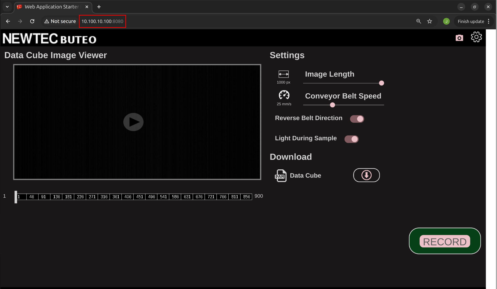
4. Connecting to the Software Interface Via LAN
You can access the Buteo software interface directly from your computer’s web browser, allowing you to control the system and download images straight to your computer without the need for a USB.
To set this up:
-
Connect via Ethernet:
Locate the two Ethernet ports on the right side of the Buteo system. Use the port labeled Local to connect your computer to the Buteo with an Ethernet cable. -
Configure Your Computer’s IP Address:
Your computer must use a static IP address in the range10.100.10.XXX(whereXXXis any number between 1 and 254, except 100).- On Linux:
Run as root (replace<interface name>with your network interface, e.g.,eth0):ifconfig <interface name> 10.100.10.200 netmask 255.255.255.0 - On Windows:
Go to Control Panel → Network and Internet → Network Connections, select your Ethernet interface, click Properties, then set:- IP address:
10.100.10.200 - Subnet mask:
255.255.255.0
- IP address:
- On Linux:
-
Access the Interface:
Open your preferred web browser and enter the following address:10.100.10.100:8080
You should now see the Buteo software interface and can operate the system directly from your computer.
Acquiring High-Quality Hyperspectral Images Step-by-Step Guide
This section provides a step-by-step guide to achieving optimal image quality with the Buteo Hyperspectral Imaging System.
Follow each subsection in order to ensure your images are sharp, well-exposed, and you have acquired optimal references for future postprocessing.
1. Adjusting Lens Focus
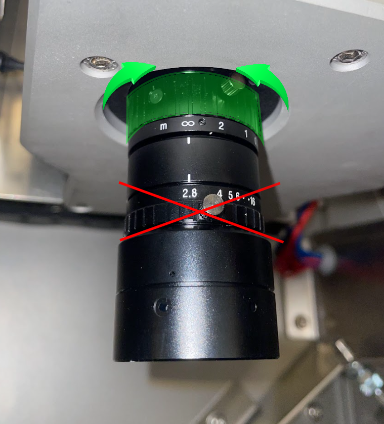
To achieve sharp images with maximum spatial resolution, it is essential to properly focus the lens onto the image plane. The camera lens has two adjustable rings: one for setting the F-number (iris) and one for focus. Focus is set using the top ring, which is marked in green in the image below. To adjust focus, carefully loosen the locking screw, rotate the focus ring until the image is sharp, and then re-tighten the screw to secure the setting.
The F-number ring should remain fixed at 2.8 and must not be adjusted.
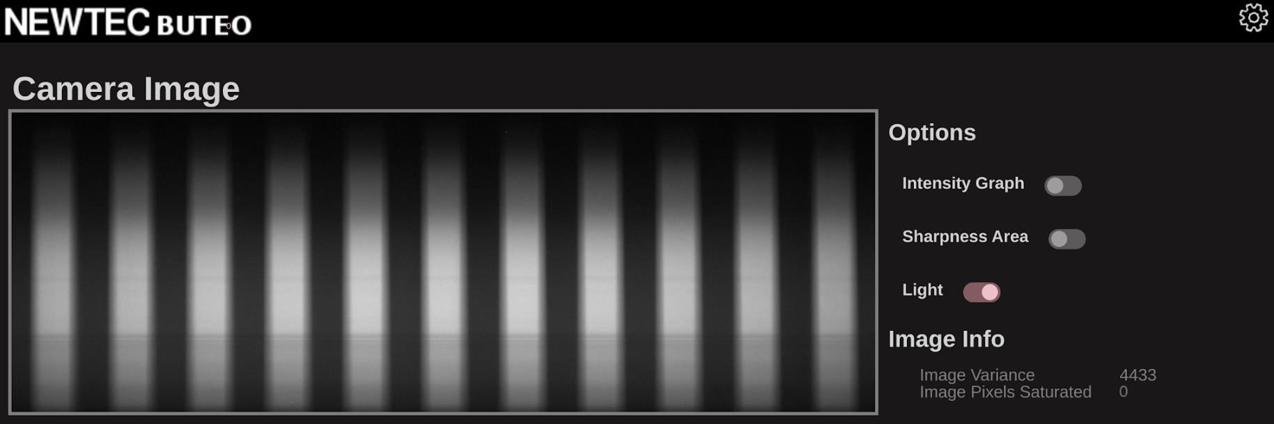
For best results, use a flat sheet of paper with distinct black and white lines such as a line grating or checkerboard pattern as a focusing target. Place this target on the conveyor belt directly under the camera within its field of view. Access the camera’s live view screen and turn on the illumination. Slowly adjust the focus ring until the lines appear crisp and well-defined on the screen. The images below illustrate this process.
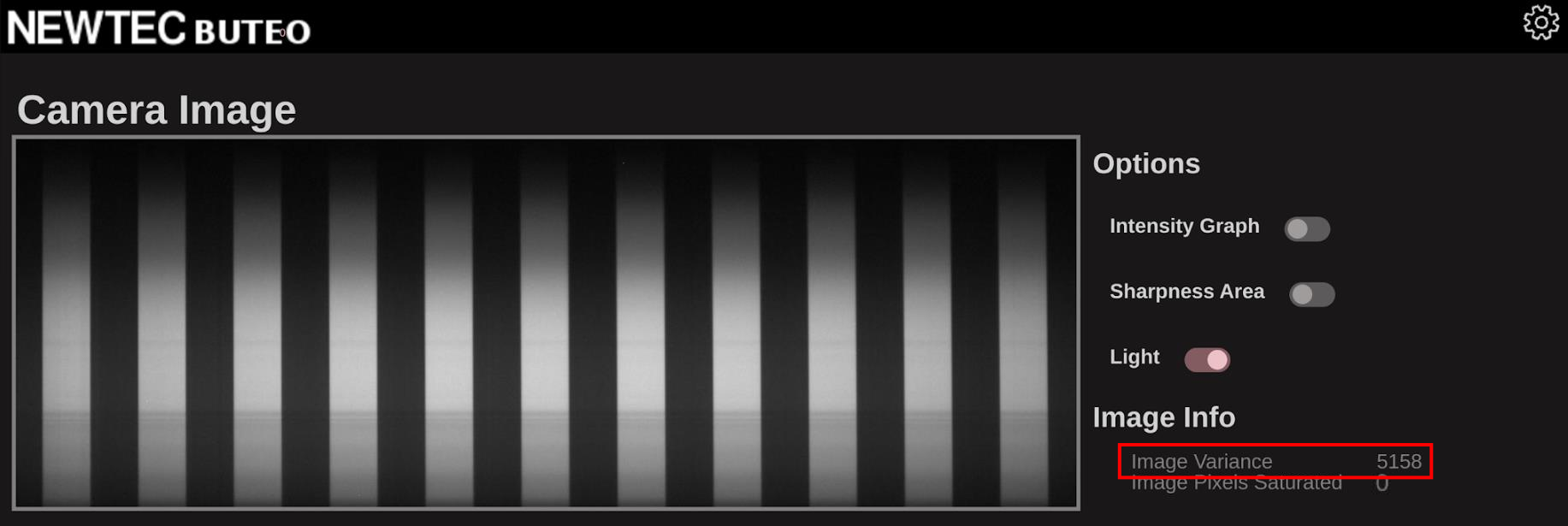
For fine adjustments, monitor the image variance value displayed on the right side of the screen; optimal focus is achieved when this value is at its maximum.
Pre-focus adjustment:
Post-focus adjustment:
If you are imaging objects that are taller and thus closer to the lens than the conveyor belt (for example, the front cover of a thick book), adjust the focus to the plane of the object rather than the belt. To do this, elevate the focusing target to the same height as the object and follow the same focusing procedure at that level.
2. Setting Crop-Top, Gain, and Exposure
To adjust the camera parameters for optimal imaging, begin by placing a white reference target directly under the camera within its field of view. Navigate to the camera’s live view screen and switch on the illumination.
Crop-Top
The first parameter to set is Crop-Top, which determines the starting point for sensor readout. Proper adjustment of this setting ensures the captured hyperspectral image spans the full spectral range of approximately 430–1700 nm.
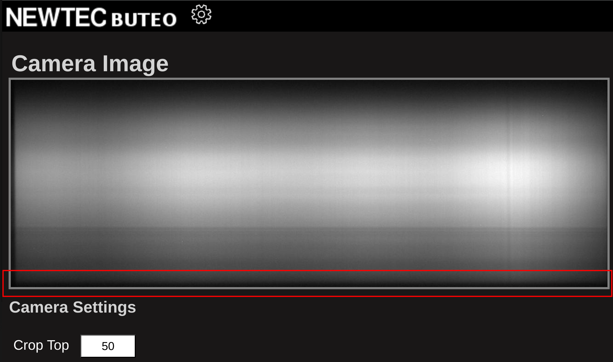
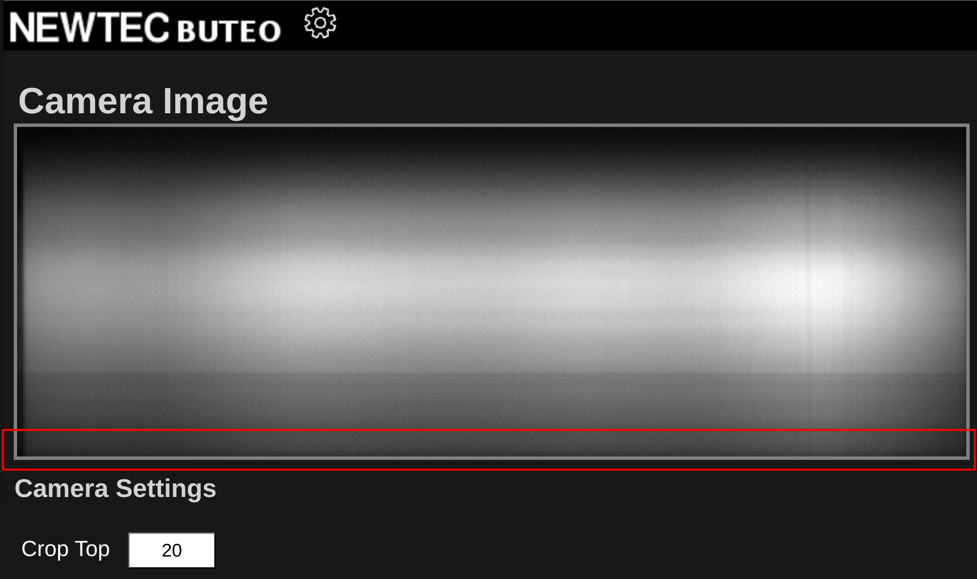
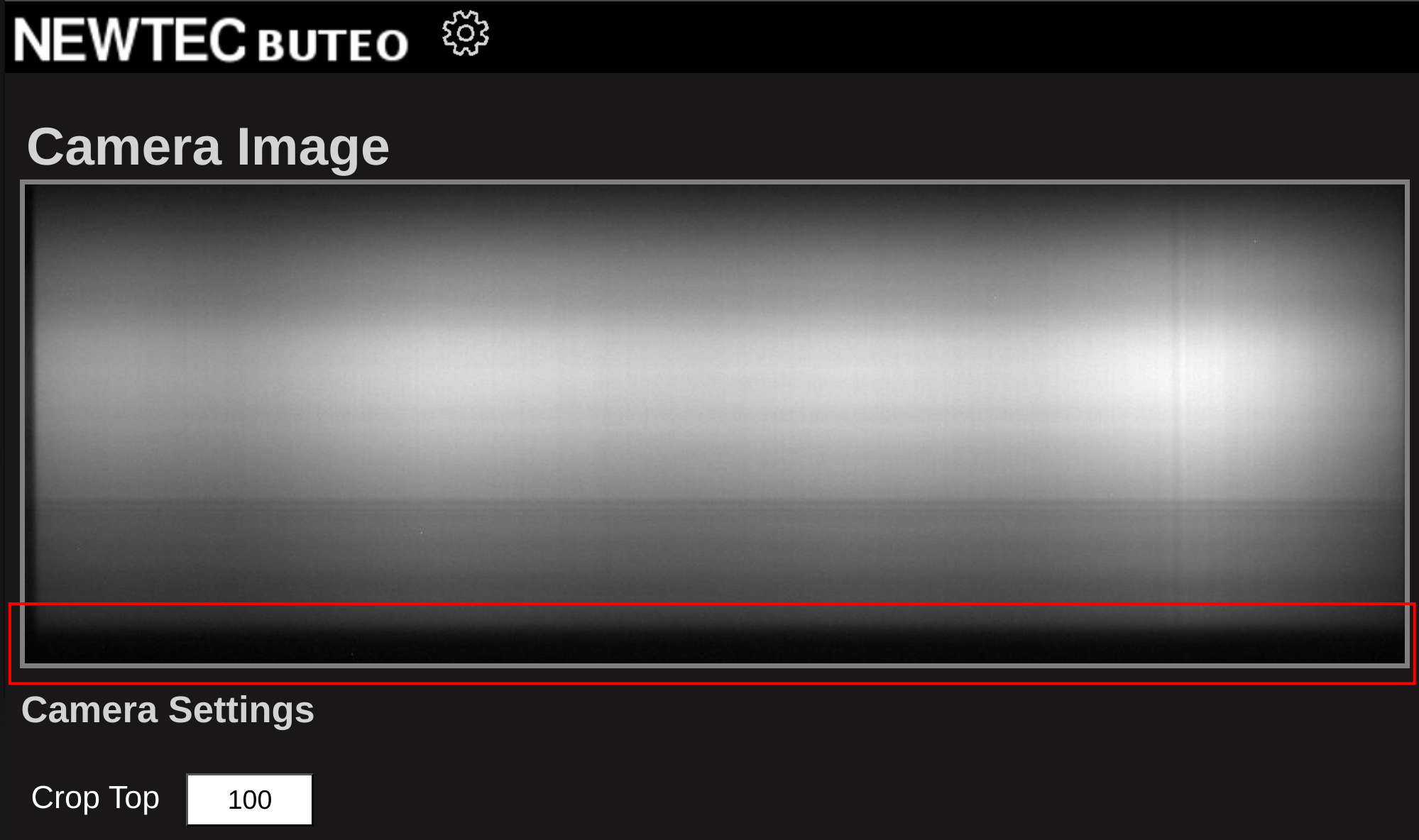
Determining the optimal Crop-Top value can be challenging, but the following approach is recommended: While viewing the white reference in live view, look for a subtle dark line near the bottom of the image. This line appears because the sensor’s sensitivity drops sharply between 1650–1700 nm. Adjust the Crop-Top value so that this drop in sensitivity is just visible at the bottom edge of the image. This ensures the output image is calibrated to end at the correct wavelength.
The images below illustrate correct and incorrect Crop-Top adjustments:
- Correct Crop-Top: The sensitivity drop is just visible at the bottom.
- Crop-Top Too Low: The sensitivity drop is not visible; part of the spectral range is missing.
- Crop-Top Too High: The sensitivity drop is too prominent; the image extends beyond the intended range.
Gain and Exposure
Adjusting gain and exposure should be performed together to achieve optimal image quality. To minimize noise and maintain a high signal-to-noise ratio, always prioritize increasing exposure before adjusting gain. This is because gain amplifies both the signal and noise, whereas increasing exposure enhances the signal without amplifying noise.
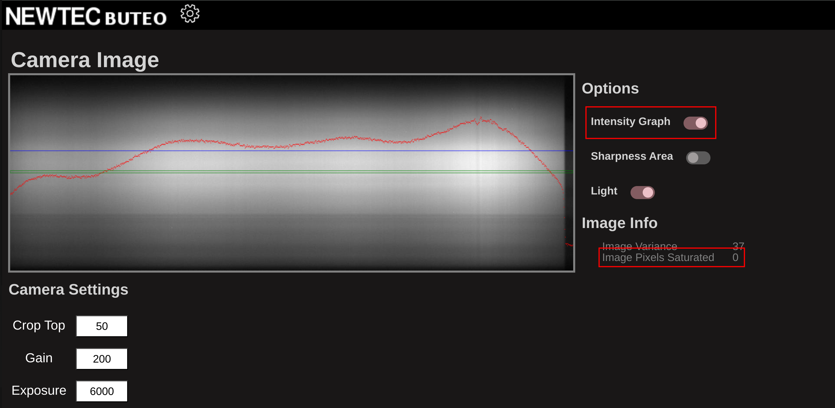
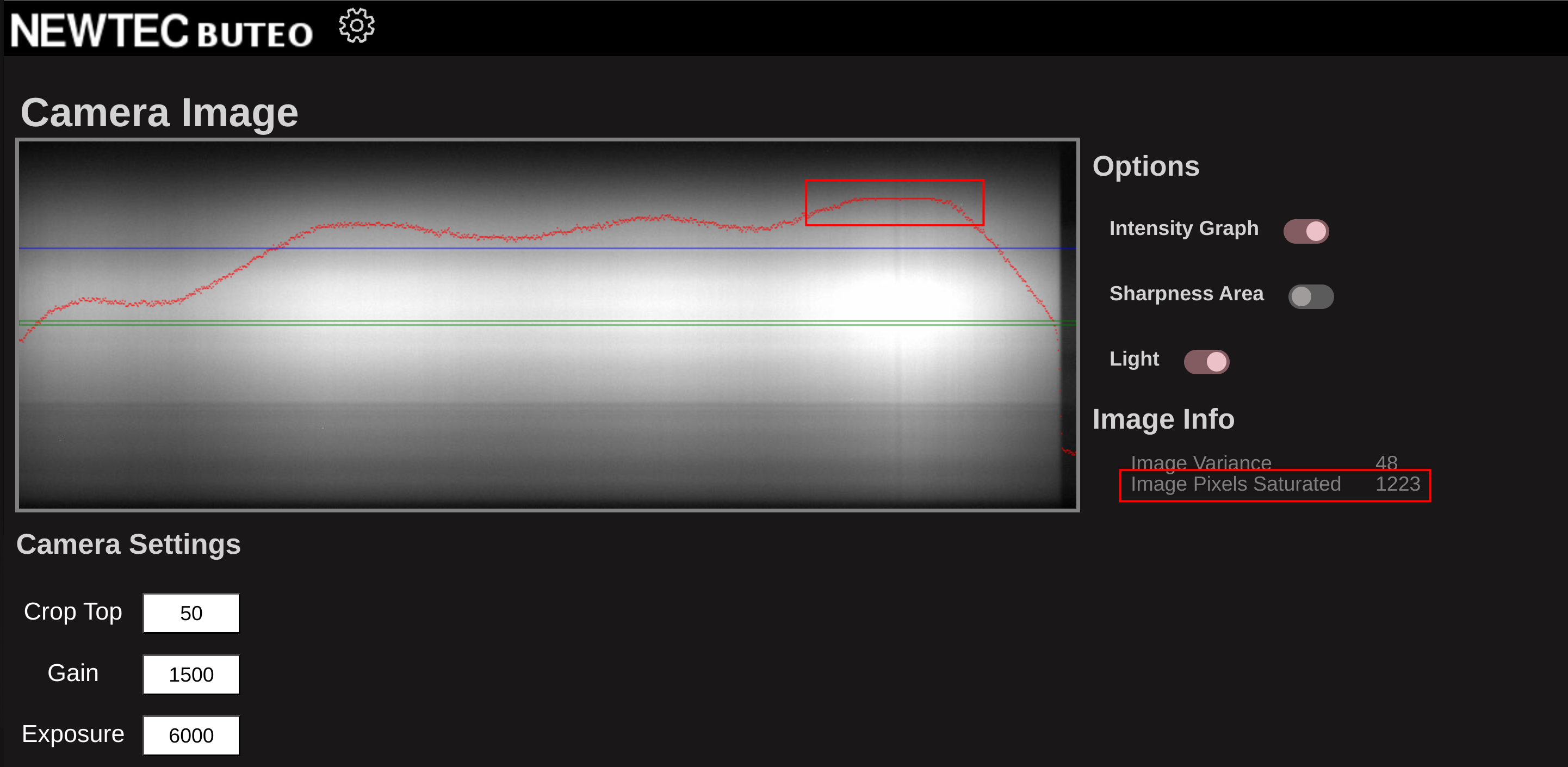
With the white reference target illuminated and positioned within the camera’s field of view, enable the intensity graph in the top right corner of the live view screen. The goal is to maximize intensity without causing overexposure. Overexposure is indicated when the intensity graph flattens at any point, or when the “image pixels saturated” counter (located on the right side of the screen) is greater than zero.
For best results, start with the gain set to 0 (corresponding to no amplification). Gradually increase the exposure until the “image pixels saturated” counter is just above zero, indicating that some pixels are nearly saturated. Then, reduce the exposure slightly (by approximately 500) to provide a margin for imaging objects that may be more reflective than the white reference.
If you reach the maximum exposure value (6000) and the image is still not saturated, incrementally increase the gain until some pixels become saturated. Once saturation is reached, reduce the gain slightly to similarly provide a margin.
The images below illustrate optimal gain and exposure settings:
-
Properly exposed image (no saturation, high intensity)
-
Overexposed image (flattened intensity, saturated pixels)
-
Underexposed image (low intensity, no saturated pixels)
3. Acquiring Proper Reference Images
Capturing accurate reference images is essential for reliable hyperspectral data. Incorrect reference acquisition can result in significant errors during post-processing. Always ensure that reference images are captured using the same Crop-Top, Gain, and Exposure settings as your sample images.
White Reference and Wavelength Calibration
For best results, capture the white reference and wavelength calibration in a single scan:
-
Prepare the System:
Follow the previous steps to set Crop-Top, Gain, and Exposure appropriately. -
Place References:
Position the white reference target and the wavelength calibration module (erbium-oxide) on the conveyor belt, just outside the camera’s field of view. -
Capture Reference Scan:
Start a hyperspectral scan to record both references in one image.
Dark Reference
To acquire a dark reference:
-
Maintain Camera Settings:
Use the same Crop-Top, Gain, and Exposure as above. -
Cover the Lens:
Place a lens cap over the camera lens to block all light. -
Capture Dark Image:
Record a hyperspectral image with the lens covered.
Save both the reference and dark images. Use these files during post-processing to normalize your data and extract accurate wavelength information. See Reflectance calibration under the HV Explorer section.
tipFor maximum accuracy, you can also include the white reference and wavelength calibration module at the edge of your actual sample scans.
In this case choose the "inline" option for the "white reference" in the HV Explorer.
Conclusion
Following the above steps will help you acquire high-quality hyperspectral images with the Buteo system. Proper focus, exposure, and reference acquisition are critical for reliable results. For detailed instructions on how to use the reference images during post-processing, please refer to HSI data processing and HV Explorer.
Additional Tips
-
Mind Your Background:
The background can affect image quality. Depending on your sample, placing it on black or white paper usually provides good scanning conditions. -
File Size and Storage:
A full-size datacube (1000 lines) requires approximately 1.2 GB of storage. Ensure your USB drive or hard disk has sufficient free space before scanning. -
Storage Device Warning:
If your USB drive or hard disk is full, the system will format the device when attempting to save a datacube. Always check available space to avoid accidental data loss. -
Recommended Storage Devices:
Use a fast USB drive (USB 3.0 or higher) or a gigabit network connection for saving data. Slow or older USB drives may take a long time to transfer large files. -
Web Interface Display:
When using the Buteo browser interface, the webpage does not automatically scale to your screen resolution. For the best experience, use full screen mode (F11) and/or zoom out (Ctrl + -).
-